Diffuser vane for a compressor device and diffuser assembly comprised thereof

A diffuser and compressor technology, applied in the field of compressor devices, can solve problems such as reducing the efficiency of variable diffuser guide vanes

Inactive Publication Date: 2015-08-26
DRESSER IND INC
View PDF6 Cites 4 Cited by
  • Summary
  • Abstract
  • Description
  • Claims
  • Application Information

AI Technical Summary

Problems solved by technology

Changes in the position of the leading edge can cause premature separation of the working fluid flow from the surface of the diffuser vane, which can reduce the efficiency of the variable diffuser vane to regulate the performance of the compressor unit

Method used


Image

  • Diffuser vane for a compressor device and diffuser assembly comprised thereof
  • Diffuser vane for a compressor device and diffuser assembly comprised thereof
  • Diffuser vane for a compressor device and diffuser assembly comprised thereof

Examples


Embodiment Construction

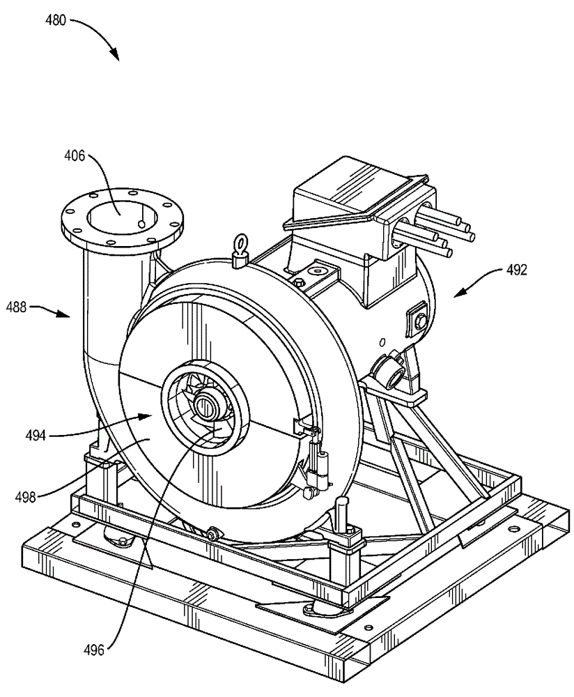
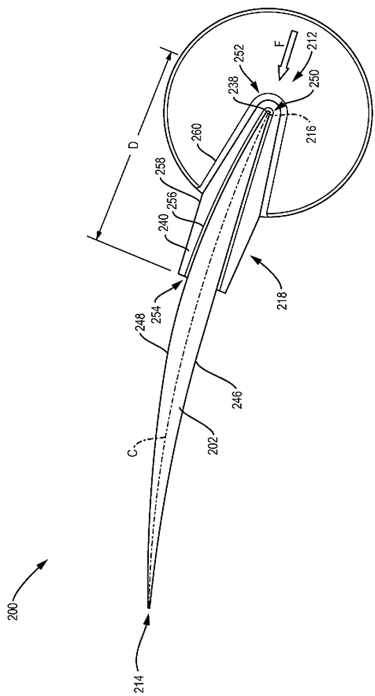
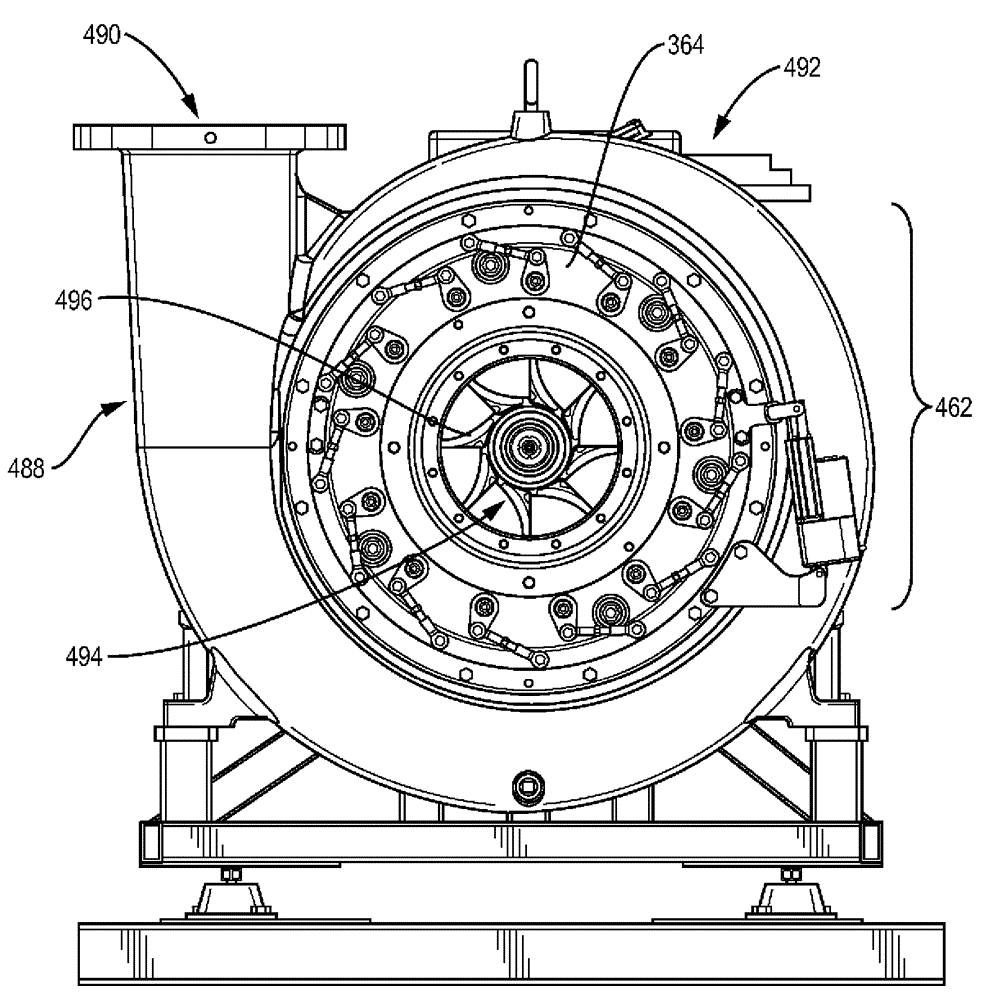
[0018] The following discussion focuses on the construction and implementation of diffuser guide vanes for better performance of compressor devices (eg centrifugal compressors). In one aspect, the design for the diffuser guide vanes allows the trailing edge to rotate to various angular positions while maintaining the orientation of the leading edge with respect to the flow direction of the working fluid flowing through the diffuser guide vanes to prevent flow separation. These designs also stabilize the diffuser vanes to prevent vibration of the diffuser vanes in response to excitation frequencies that can damage the diffuser vanes.

[0019] These diffuser vanes are utilized in a diffuser assembly whose operation can adjust the performance of the compressor. The diffuser assembly may include a plurality of diffuser vanes. In one example, the diffuser assembly couples the diffuser vanes to a conventional actuator to facilitate adjustment of the position of the trailing edge, for ...


PUM


Abstract

Embodiments of a diffuser vane comprise a vane body with a leading edge and a trialing edge that can rotate about the leading edge to improve performance of a compressor device. This configuration maintains the position of the leading edge on the diffuser vane relative to the orientation of the working fluid. In one embodiment, the diffuser vane incorporates a support element that couples with the vane body. The support element counteracts stimulating frequencies to reduce vibration of the vane body. The diffuser vane can also comprise an armature, which couples with a force coupler to facilitate rotation of the trailing edge when in position in a compressor device.

Description

Technical field [0001] The subject matter disclosed herein relates to compressor devices (e.g., centrifugal compressors), and particularly to diffusers or diffuser guide vanes for compressor devices. Background technique [0002] Compressor devices, such as centrifugal compressors, use diffuser assemblies to convert the kinetic energy of the working fluid into static pressure by slowing down the velocity of the working fluid through the expansion volume region. An example of a diffuser assembly utilizes several diffuser vanes arranged around the circumference of the impeller. The design (e.g., shape and size) of the diffuser vanes, combined with the orientation of the leading and trailing edges of the diffuser vanes with respect to the working fluid flow, generally determines how the diffuser vanes are secured within the diffuser assembly. [0003] To add more improvements and flexibility to the design, some examples of diffuser assemblies include variable diffuser vanes. These t...

Claims


Application Information

Patent Timeline
Patent Type & Authority Applications(China)
IPC IPC(8): F04D29/46
CPCF04D29/462F05D2250/52
Inventor D.E.胡斯泰
Owner DRESSER IND INC
Why Eureka
Try Eureka