Refrigeration device comprising an ice maker with double stops

A technology for refrigeration appliances and ice machines, which is applied in ice making, ice making, household appliances, etc., which can solve the problems of short service life of ice cube trays, and achieve the effect of simple structure and improved service life

Active Publication Date: 2015-08-26
BSH BOSCH & SIEMENS HAUSGERAETE GMBH
View PDF6 Cites 0 Cited by
  • Summary
  • Abstract
  • Description
  • Claims
  • Application Information

AI Technical Summary

Problems solved by technology

Due to the constant deformation of the ice cube tray and the low ambient temperature, the ice cube tra

Method used


Image

  • Refrigeration device comprising an ice maker with double stops
  • Refrigeration device comprising an ice maker with double stops
  • Refrigeration device comprising an ice maker with double stops

Examples


Embodiment Construction

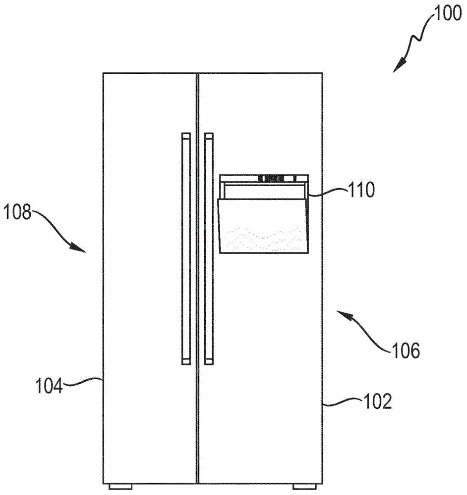
[0028] figure 1 A refrigerator is shown as an example for a refrigeration appliance 100 , which has a right refrigeration appliance door 102 and a left refrigeration appliance door 104 on its front side of the refrigeration appliance. The refrigerator is used, for example, to cool food and includes a coolant circuit with an evaporator (not shown), a compressor (not shown), a condenser (not shown) and a flow mechanism (not shown).

[0029] The evaporator is designed as a heat exchanger in which, after expansion, the liquid coolant is evaporated by absorbing heat from the medium to be cooled, namely the air in the interior of the refrigerator.

[0030] The compressor is a mechanically driven component which draws coolant vapor from the evaporator and discharges it at a higher pressure to the condenser.

[0031] The condenser is designed as a heat exchanger in which, after compression, the evaporated coolant is liquefied by imparting heat to the external coolant, ie the ambient...


PUM


Abstract

The invention relates to a refrigeration device comprising an ice maker (110) which has a rotatably mounted ice cube tray (202) about a rotational axis. According to the invention, the ice maker (110) comprises two stops (206) for limiting the rotational movement of the ice cube tray (202) about the rotational axis (D).

Description

technical field [0001] The invention relates to a refrigeration appliance having an ice maker with an ice cube tray mounted rotatably about a rotational axis. Background technique [0002] Refrigeration appliances, in particular refrigeration appliances designed as domestic appliances, are known and are used in households in the domestic or catering sector to store perishable food and / or beverages at a defined temperature. [0003] In an ice maker of this type of refrigeration appliance, the ice cubes formed in the ice cube tray are released from the mold in such a way that the ice cube tray is twisted by means of a drive until the ice cube tray is turned upside down and the ice cubes come out of the ice cube tray. falls out of the ice cube tray. Starting from a defined position, this rotational movement of the ice cube tray is stopped by a stop. Because the ice cube tray is designed flexibly, the ice cube tray undergoes a twist by contact with the stop, which eventually c...

Claims


Application Information

Patent Timeline
IPC IPC(8): F25C5/06
CPCF25C5/06F25C2305/022F25C2305/0221F25C1/04
Inventor J·博里德尔G·施密特
Owner BSH BOSCH & SIEMENS HAUSGERAETE GMBH
Why Eureka
Try Eureka