Imager module and method for producing an imager module

An imager and support module technology, applied in the directions of instrumentation, image communication, transportation and packaging, can solve the problems of defocusing, damage to image quality, permanent deformation of the receiving part of the lens group, etc., and achieve a low-cost, accurate and reliable structure. Effect

Inactive Publication Date: 2015-08-26
ROBERT BOSCH GMBH
View PDF8 Cites 6 Cited by
  • Summary
  • Abstract
  • Description
  • Claims
  • Application Information

AI Technical Summary

Problems solved by technology

However, said greater clamping can lead to permanent deformation of the optics receiver and thus to defocusing
In addition, scratche...

Method used


Image

  • Imager module and method for producing an imager module
  • Imager module and method for producing an imager module
  • Imager module and method for producing an imager module

Examples


Embodiment Construction

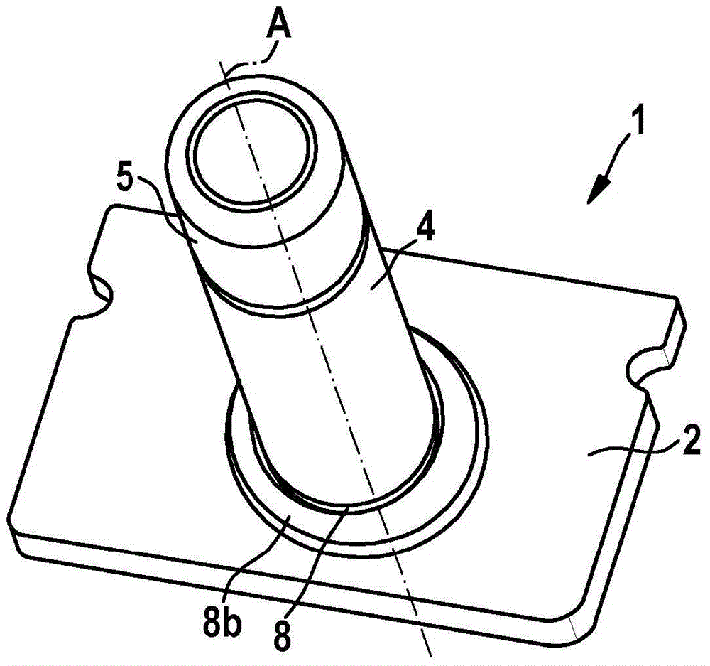
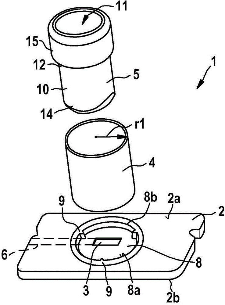
[0031] according to Figures 1 to 5 The imager module 1 has a sensor carrier 2 , an image sensor 3 mounted on the sensor carrier 2 , a substantially tubular clamping sleeve made of elastic material, and an optics 5 .

[0032]The sensor carrier 2 is used for mounting and connecting the image sensor 3 and for receiving the clamping sleeve 4 . The sensor carrier 2 can be, for example, a MID (Molded Interconnect Device) or an injection-moulded circuit carrier and has on its underside 2 b wires or conductor tracks 6 , by means of which the image sensor 3 is connected. A recess 7 is formed in the sensor carrier 2 . In flip-chip technology, image sensor 3 is aligned by means of its sensitive surface to mirror assembly 5 via recess 7 and is connected to conductor track 6 , for example via solder bumps (not shown in further detail). In this case, the sensor may in particular be unencapsulated and be oriented with its sensitive surface through the cutout without further covering; howe...


PUM


Abstract

The invention relates to an imager module (1) for a camera system (24), wherein the imager module (1) at least comprises: a sensor carrier (2), an image sensor (3) accommodated on the sensor carrier (2), and a lens (5). In this case, provision is made for an elastically deformable clamping device (4) to be braced between the lens (5) and the sensor carrier (2). The clamping device (4) can be elastically deformed more particularly between regions (16) of the outer surface of the lens (5) and supporting means (9) of a supporting device (8) in a plane substantially perpendicular to an axis (A) of symmetry of the lens (5) or an optical axis of the imager module (1).

Description

Background technique [0001] Camera systems used in vehicles usually have a camera housing, a circuit carrier with further electronic components, and an imager module, which is connected to the circuit carrier. The imager module itself typically has an image sensor, a sensor carrier for accommodating the image sensor, and an optics. The optics are connected to the sensor carrier via, for example, optics receptacles or lens holders. Thus, the image sensor and the optics define the optical axis. The image sensor can be mounted on the sensor carrier directly or via the chip carrier and connected via the sensor carrier, for example by means of conductor tracks of the sensor carrier that lead to the circuit carrier. [0002] The imager module is initially mounted as a unit and focused by adjusting the optics along the optical axis relative to the image sensor. The completed imager module can then be connected to the circuit carrier and accommodated in the camera housing. [0003...

Claims


Application Information

Patent Timeline
IPC IPC(8): G03B17/12G03B43/00G02B7/02
CPCG03B43/00G02B7/023H04N5/2254G02B7/025H04N5/2257G03B17/12G02B7/026H04N23/50H04N23/55Y10T29/49828H04N23/57G02B7/02B60R1/00H04N23/54H04N23/51
Inventor N·鲍尔U·阿佩尔
Owner ROBERT BOSCH GMBH
Why Eureka
Try Eureka