Movably detachable pan handle

A pot handle and handle technology, which is applied in the field of movable and detachable pot handles, can solve the problems of large space occupation, high transportation cost, and large product packaging, and achieve the effect of simple and reliable structure, low precision requirements, and simple assembly

Active Publication Date: 2015-09-02
金华市卡德罗尼科技有限公司
View PDF8 Cites 5 Cited by
  • Summary
  • Abstract
  • Description
  • Claims
  • Application Information

AI Technical Summary

Problems solved by technology

[0002] At present, the fixed connection methods of the handle and the pot body can be divided into non-detachable and detachable two structures: the non-detachable structure is that the pot handle is directly welded or riveted to the pot body through the handle connection seat, and its advantage is that the connection is firm and not It will loosen; its disadvantages: first, the product packaging and transportation are bulky, and the packaging and transportation costs are high; second, it is difficult to put together with other pots and pots when stored at home, which takes up a lot of space and is not conducive to storage and placement, is not conducive to cleaning
The detachable structure is that the pot handle is connected to the pot body through screws, etc., and can be disassembled by tools. Compared with the non-detachable structure, it solves the problem of large product packaging and high transportation costs. However, when using it at home, manual tools are required for disassembly. It can only be disassembled, and it does not have a real quick disassembly. There are also the above-mentioned problems of inconvenient placement, storage and cleaning.
[0003] The existing detachable handles or detachable pot ears are not stable in combination with the pot body, easy to loosen, and the internal parts require high precision and are difficult to assemble

Method used


Image

  • Movably detachable pan handle
  • Movably detachable pan handle
  • Movably detachable pan handle

Examples


Embodiment Construction

[0022] Below in conjunction with specific embodiment, further illustrate the present invention. It should be understood that these examples are only used to illustrate the present invention and are not intended to limit the scope of the present invention. In addition, it should be understood that after reading the teachings of the present invention, those skilled in the art can make various changes or modifications to the present invention, and these equivalent forms also fall within the scope defined by the appended claims of the present application.

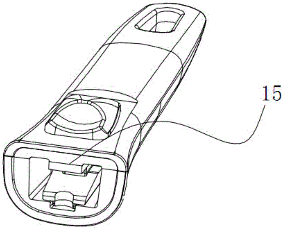
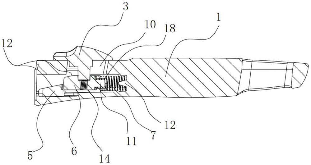
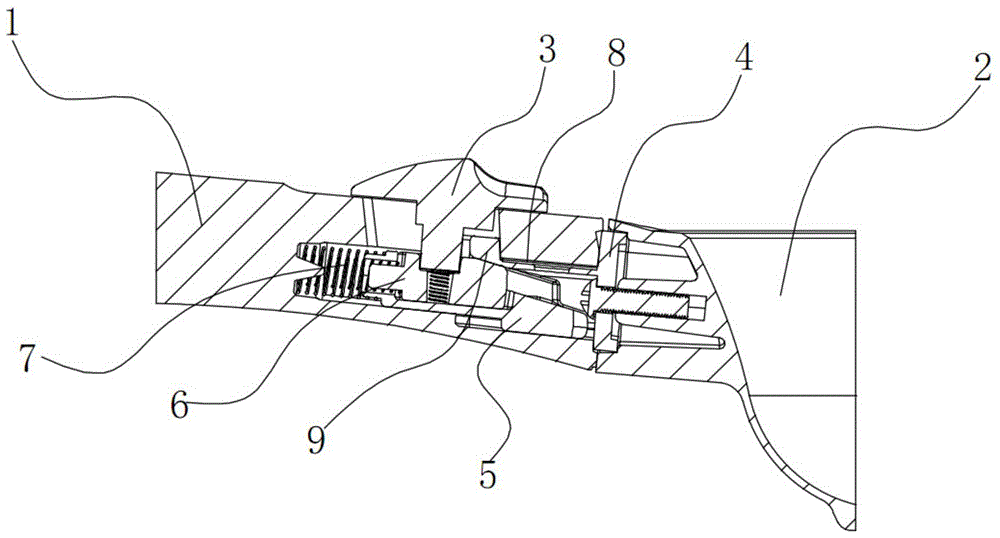
[0023] Such as Figure 1-8 As shown, the embodiment of the present invention relates to a movable and detachable pot handle, which includes a handle 1 and a pot handle connecting seat 4 installed on the pot body 2. One end of the handle 1 is arranged with an inner cavity with an open end. A rectangular sliding through hole 10 is opened on the upper side of the inner cavity, and a wedge-shaped slider 5 is slidably installed on ...


PUM


Abstract

The invention relates to a movably detachable pan handle which comprises a handle and a pan handle connection base arranged on a pan body. An inner cavity with one end open is formed in one end of the handle, a wedge slide is arranged at the bottom of the inner cavity in a sliding mode, the upper end surface of the wedge slide is inserted into an slidable upper slide, a sliding button is arranged on the upper end surface of the handle, the lower end of the sliding button penetrates through a rectangular through hole to be connected with the upper slide, and one end of the wedge side is connected with the inner wall of the inner cavity through an elastic part I; a groove is formed in the upper end of the pan handle connection base and is inserted into the inner cavity of the handle, correspondingly, a convex block is arranged at the top of the open end of the inner cavity and is inserted into the groove, and the front end of the groove in the pan handle connection base is clamped between the convex block of the inner cavity of the handle and the upper slide. An interlocking mechanism arranged in the movably detachable pan handle is simple and reliable in structure, has a low accuracy requirement on interior parts, is simple to assemble, does not need screws for connection on the whole, is firm and not loosened after the pan handle is combined with the pan body, and is safer and more reliable.

Description

technical field [0001] The invention relates to the field of pot accessories, in particular to a movable and detachable pot handle. Background technique [0002] At present, the fixed connection methods of the handle and the pot body can be divided into non-detachable and detachable two structures: the non-detachable structure is that the pot handle is directly welded or riveted to the pot body through the handle connection seat, and its advantage is that the connection is firm and not It will loosen; its disadvantages: first, the product packaging and transportation are bulky, and the packaging and transportation costs are high; second, it is difficult to put together with other pots and pots when stored at home, which takes up a lot of space and is not conducive to storage And placed, is also not conducive to cleaning. The detachable structure is that the pot handle is connected to the pot body through screws, etc., and can be disassembled by tools. Compared with the non-...

Claims


Application Information

Patent Timeline
Patent Type & Authority Applications(China)
IPC IPC(8): A47J45/07
Inventor 何廷贵
Owner 金华市卡德罗尼科技有限公司
Why Eureka
Try Eureka