Balloon dilatation intramedullary nail

An intramedullary nail and balloon technology, which is applied in the field of balloon expansion intramedullary nails, can solve the problems of poor anti-rotation and anti-separation and displacement effects, difficult surgical operations, restricting the use of intramedullary nails, etc. Anti-separation displacement and anti-rotation, good anti-separation displacement and anti-rotation, and the effect of promoting bone growth

Active Publication Date: 2015-09-02
JIANGSU CHANGMEI MEDICAL INSTR CO LTD
View PDF6 Cites 1 Cited by
  • Summary
  • Abstract
  • Description
  • Claims
  • Application Information

AI Technical Summary

Problems solved by technology

[0003] 1. The diameter of the bone marrow cavity limits the use of intramedullary nails;
[0004] 2. There are many intramedullary nail components, and the operation is too cumbersome, which prolongs the operation time;
[0005] 3. The intramedullary nail needs to make a hole on the transverse surface of the bone. It will destroy the cortical bone when used in conjunction with the internal screw hole of the intramedullary nail. The operation is difficult and risky
Although it can be flexed and shaped freely before expansion, and it can be quickly hardened when it fits the medullary cavity, but generally they are used to inject UV glue into the balloon when fractures occur. UV glue can harden quickly, but it cannot be removed after the fracture.
At the same time, due to the smooth outer wall of the balloon, the anti-rotation and anti-separation displacement effects are not very good

Method used


Image

  • Balloon dilatation intramedullary nail
  • Balloon dilatation intramedullary nail
  • Balloon dilatation intramedullary nail

Examples


Embodiment Construction

[0050] The present invention will now be further described with reference to specific embodiments. These drawings are all simplified schematic diagrams only to illustrate the basic structure of the present invention in a schematic manner, so they only show the structures related to the present invention.

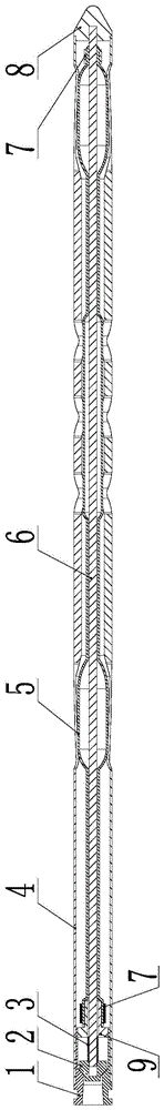
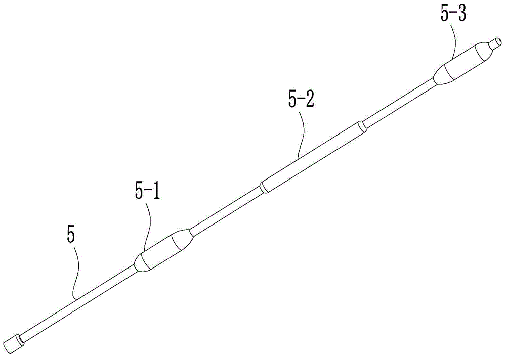
[0051] like Figure 1 to Figure 7 As shown, a balloon-expandable intramedullary nail includes an outer tube 4, a balloon 5 and a central rod 6, the balloon 5 is arranged in the outer tube 4, the central rod 6 is arranged in the balloon 5, and the front ends of the central rods 6 are respectively It forms a sealing connection with the front end of the balloon 5 and the front end of the outer tube 4 .

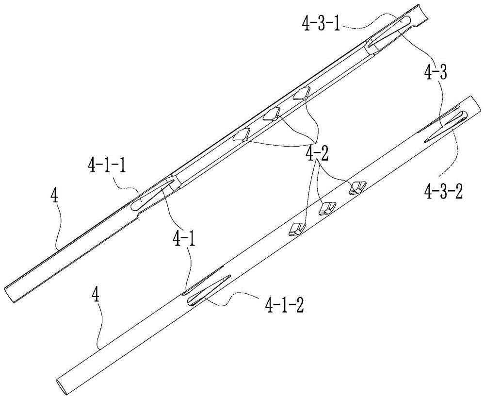
[0052]The front part of the outer tube 4 is provided with a front tube body radial expansion part 4-3, the rear part of the outer tube 4 is provided with a rear tube body radial expansion part 4-3; the front part of the balloon 5 and the front tube body radial expansion part ...


PUM


Abstract

The invention relates to a balloon dilatation intramedullary nail which comprises an outer tube, a balloon and a center rod. The balloon is arranged in the outer tube, the center rod is arranged in the balloon, the front end of the center rod is connected with the front end of the balloon and the front end of the outer tube in a sealed mode, the rear end of the center rod extends out of the rear end of the balloon, and an inner liquid inlet is formed between the rear end of the center rod and the rear end of the balloon; front tube body radial expansion parts are arranged on the front portion of the outer tube, rear tube body radial expansion parts are arranged on the rear portion of the outer tube, a front balloon body expansion part is formed in the front portion, opposite to the positions of the front tube body radial expansion parts, of the balloon, and a rear balloon body expansion part is formed in the rear portion, opposite to the positions of the rear tube body radial expansion parts, of the balloon. According to the balloon dilatation intramedullary nail, the front portion, the middle portion and the rear portion of the outer pipe expand rapidly through expansion of the balloon, and the effect of being resistant to separation and displacement and rotation between bones is enhanced.

Description

technical field [0001] The invention relates to a balloon-expanding intramedullary nail. Background technique [0002] The existing intramedullary nails in the domestic market are generally composed of intramedullary nail rods, locking nails, lag screws, cap screws and other components. The intramedullary nail rod is provided with a locking screw positioning hole and a connecting sleeve positioning groove, although the intramedullary nail can be fixed by means of locking nails and lag screws to prevent bone rotation deformity. However, the existing intramedullary nails still have the following disadvantages: [0003] 1. The diameter of the marrow cavity limits the use of intramedullary nails; [0004] 2. There are many components of intramedullary nail, the operation is too cumbersome, and the operation time is prolonged; [0005] 3. The intramedullary nail needs to have a hole in the transverse surface of the bone. When used in conjunction with the internal screw hole of...

Claims


Application Information

Patent Timeline
IPC IPC(8): A61B17/72
CPCA61B17/00234A61B17/7216
Inventor 李国来李东明张文娟
Owner JIANGSU CHANGMEI MEDICAL INSTR CO LTD
Why Eureka
Try Eureka