Patella locking plate
A technique for locking the plate, patella, applied in the direction of outer plate, fixator, internal bone synthesis, etc.
- Summary
- Abstract
- Description
- Claims
- Application Information
AI Technical Summary
Problems solved by technology
Method used
Image
Examples
Embodiment 1
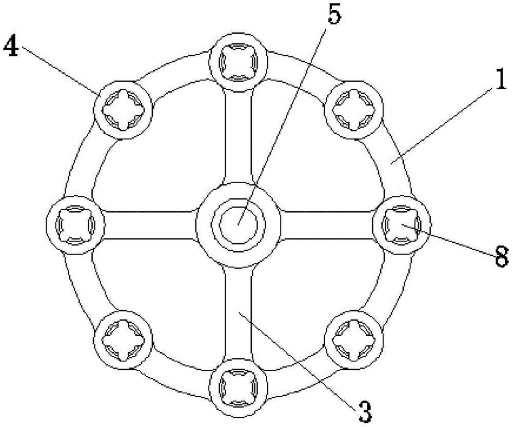
[0019] like figure 1 and Figure 4 The patella locking plate shown includes a bone plate main body 1 and a shaper 2, the front of the bone plate main body 1 is in the shape of a ring, the side of the bone plate main body 1 is arc-shaped, and the bone plate The main body 1 is connected with two intersecting fixing strips 3, and the annular surface of the bone plate main body 1 is provided with 8 or more threaded holes 4, and the two ends of the fixing strips 3 are respectively connected Inside a threaded hole 4 , the shaper 2 is connected in the threaded hole 4 , and a pressure hole 5 is opened at the intersection of the two fixing bars 3 . The bone plate main body 1 is made of pure titanium or stainless steel. The bone plate main body 1 is made of pure titanium or stainless steel; the side curvature of the bone bone plate main body 1 matches the outer surface curvature of the human patella; the shaper 2 is composed of an outer hexagon and a circumscribed The threaded end is...
Embodiment 2
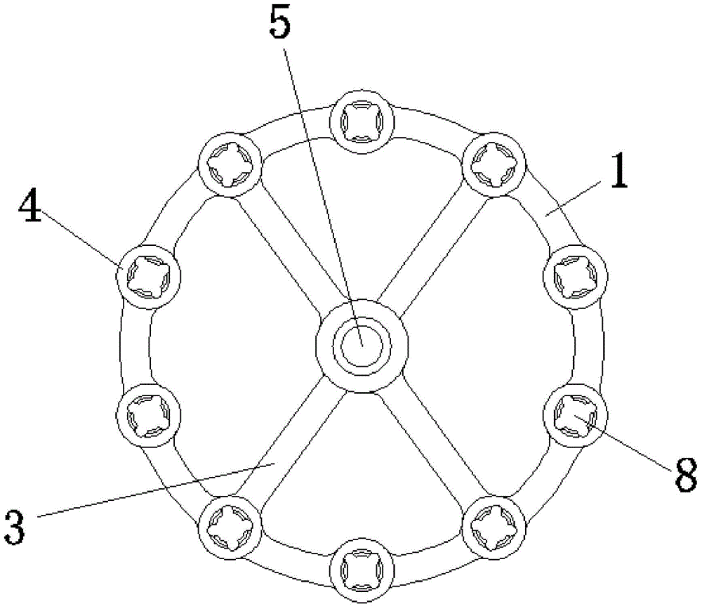
[0022] The structure of the second embodiment is roughly the same as that of the first embodiment, and the difference lies in the number of threaded holes 4 provided on the annular surface of the bone plate main body 1. The structure of the bone plate main body 1 in the second embodiment is as follows: figure 2 As shown, the annular surface of the bone plate main body 1 is provided with 10 threaded holes 4, the angle between the two adjacent threaded holes 4 is 36°, and the two The fixing strip 3 is connected in the bone plate main body 1 at an included angle of 72°. The number of locking screws that need to be connected will be different according to the actual situation. In the second embodiment, there are 10 threaded holes 4 on the main body 1 of the bone plate. At this time, people can connect 10 locking screws, which has the advantages of simple structure and high safety. Suitable for clinical needs, the bone plate has the advantages of high bending strength.
Embodiment 3
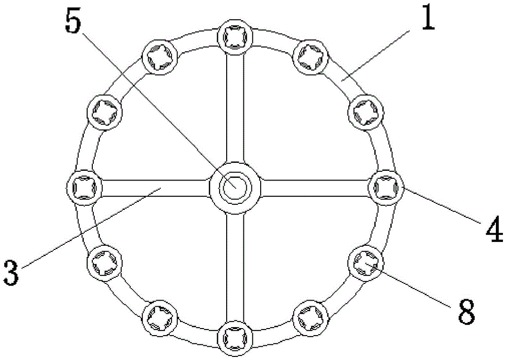
[0024] The structure of the third embodiment is roughly the same as that of the first embodiment, the difference lies in the difference in the number of threaded holes 4 provided on the annular surface of the bone plate main body 1, the structure of the bone plate main body 1 in the third embodiment is as follows image 3 As shown, the annular surface of the bone plate main body 1 is provided with 12 threaded holes 4, the angle between the two adjacent threaded holes 4 is 30°, and the two The fixing strips 3 are connected in the main body 1 of the bone plate in the shape of a right cross. The number of locking screws that need to be connected will be different according to the actual situation. In the third embodiment, there are 12 threaded holes 4 on the main body 1 of the bone plate. At this time, people can connect 12 locking screws, which has the advantages of simple structure and high safety. Suitable for clinical needs, the bone plate has the advantages of high bending s...
PUM
 Abstract
Description
Claims
Application Information
 - R&D
- Intellectual Property
- Life Sciences
- Materials
- Tech Scout
- Unparalleled Data Quality
- Higher Quality Content
- 60% Fewer Hallucinations
Browse by: Latest US Patents, China's latest patents, Technical Efficacy Thesaurus, Application Domain, Technology Topic, Popular Technical Reports.
© 2025 PatSnap. All rights reserved.Legal|Privacy policy|Modern Slavery Act Transparency Statement|Sitemap|About US| Contact US: help@patsnap.com


