
Dual-drive jogging holder

A dynamic clamping and dual-drive technology, applied in the field of manufacturing, can solve problems such as complex structures, achieve the effects of simplifying the mechanical structure, minimizing the motion transmission chain, and improving motion accuracy

Inactive Publication Date: 2015-09-02
SHANDONG UNIV OF TECH
View PDF10 Cites 0 Cited by
  • Summary
  • Abstract
  • Description
  • Claims
  • Application Information

AI Technical Summary

Problems solved by technology

[0004] Although many scholars at home and abroad have studied micro-motion grippers, most of the structures are relatively complex, and simplifying the structure can not only reduce the manufacturing cost, but also effectively improve the motion accuracy.

Method used


Image

  • Dual-drive jogging holder

Examples


Embodiment Construction

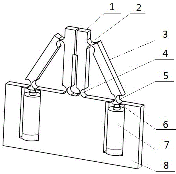
[0010] The clamping fingers 1 are two whose lower ends are connected to the fixed platform 8 through the elastic rotating pair 4 and installed face to face. The two branch chains are symmetrically distributed on both sides of the symmetrical plane of the two clamping fingers 1. It includes a connecting rod 3, an elastic thin plate 6 and a micro-displacement driving device 7, wherein one end of the connecting rod 3 is connected to the upper end of the clamping finger 1 through the elastic rotating pair 2, and the other end is connected to the elastic thin plate 6 through the elastic rotating pair 5. The middle part of one side is fixedly connected, the middle part of the other side of the elastic thin plate 6 is fixedly connected with one end of the micro-displacement driving device 7, the other end of the micro-displacement driving device 7 is fixedly connected with the fixed platform 8, and both ends of the elastic thin plate 6 are connected with the fixed platform. 8 fixed co...


PUM


Abstract

The invention provides a dual-drive jogging holder. The dual-drive jogging holder comprises clamping fingers, a fixed platform and two branches, wherein the two branches are connected between the clamping fingers and the fixed platform. The dual-drive jogging holder is characterized in that the lower ends of the two clamping fingers are connected with the fixed platform through an elastic revolute pair and the two clamping fingers are arranged in a face-to-face way, the two branches are symmetrically distributed at the two sides of symmetric surfaces of the two clamping fingers, each branch comprises a connecting rod, an elastic thin plate and a micrometric displacement driving device, one ends of the connecting rods are connected with the upper ends of the clamping fingers through the elastic revolute pair, and the other ends of the connecting rods are fixedly connected with the middle parts of one sides of the elastic thin plates; one ends of the micrometric displacement driving devices are fixedly connected with the middle parts of the other sides of the elastic thin plates, and the other sides of the micrometric displacement driving devices are fixedly connected with the fixed platform, and the two ends of the elastic thin plates are both fixedly connected with the fixed platform. The dual-drive jogging holder provided by the invention has the advantages of being simple in structure, high in precision, being capable of independently controlling the two clamping fingers and the like.

Description

technical field [0001] The invention belongs to the field of manufacturing technology, and in particular relates to a double-drive micro-motion gripper. Background technique [0002] With the development of microfabrication technology, microelectronic technology and MEMS technology, micromachining and micromanipulation technology have developed rapidly. The field shows broad application prospects. [0003] The electrostatically driven micro-gripper developed by Kim et al. in the United States adopts a comb-shaped electrostatically driven structure, and the main structure is composed of polysilicon. The piezoelectric body-driven micro-gripper developed by the University of Karlsruhe (Univ. of Karlsruhe, Germany) consists of a piezoelectric driver, a flexible hinge amplification mechanism and a clamping arm. Heiserman, David L et al. have developed a micro-gripper driven by a piezoelectric film. Houston et al. developed a shape memory alloy actuated microgripper. Domestic ...

Claims


Application Information

Patent Timeline
IPC IPC(8): B25J15/08
CPCB25J15/08
Inventor 宫金良张彦斐郑洋洋
Owner SHANDONG UNIV OF TECH
Learn More