An Injection Molding Production Process for Reducing Warping of Plastic Flat Plates

A production process and plastic technology, which is applied in the field of production requirements of plastic shading plates for photographic lamps, can solve the problems of prolonged molding time, expansion of cooling water pipe diameter, and increase in injection cost, so as to reduce warpage deformation, shorten production time, The effect of simple process flow

Active Publication Date: 2018-01-23
莆田市多容光学电子有限公司
View PDF5 Cites 2 Cited by
  • Summary
  • Abstract
  • Description
  • Claims
  • Application Information

AI Technical Summary

Problems solved by technology

Improperly designed cooling system will lengthen the molding time and increase the cost; uneven cooling will further cause warping and deformation of plastic products
In the prior art, cooling water pipes are commonly used at the mold cavity. In order to enhance the cooling effect, the number of cooling water pipes is increased, and the diameter of the cooling water pipes is enlarged. This not only increases the cost of injection molding, but also the large number of cooling water pipes cannot be evenly distributed due to the limitation of the mold structure. Easy to cool unevenly and cause further warping and deformation of plastic products

Method used


Image

  • An Injection Molding Production Process for Reducing Warping of Plastic Flat Plates
  • An Injection Molding Production Process for Reducing Warping of Plastic Flat Plates

Examples


Embodiment 1

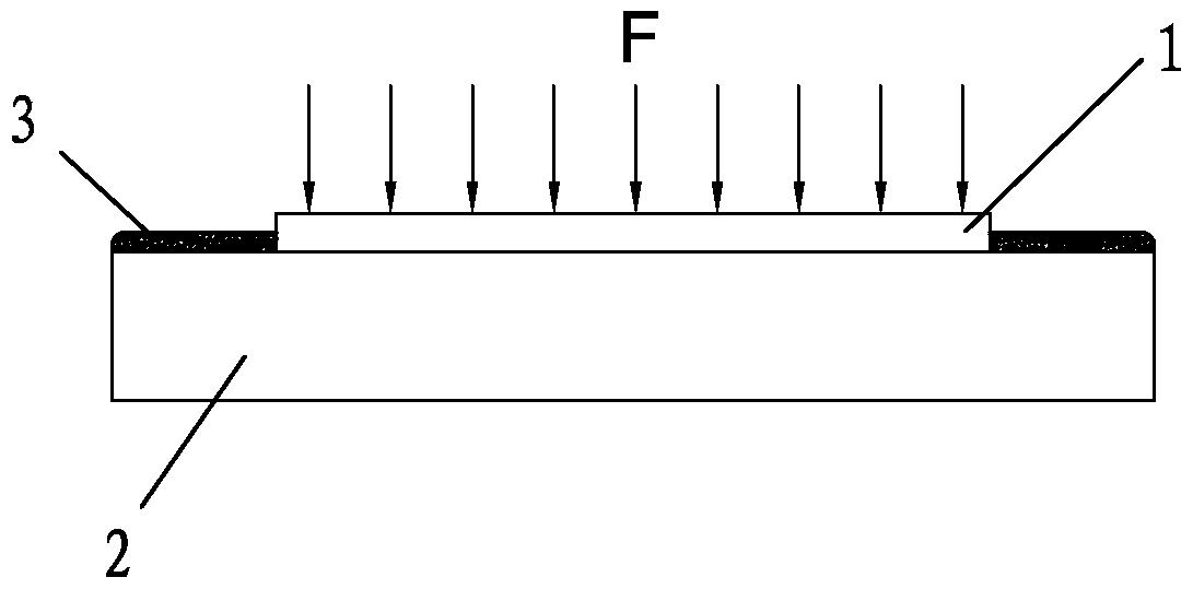
[0034] Example 1: Please refer to figure 1 Shown step 1, setting a smooth platform 2, to described smooth platform 2

[0035] Add liquid 3 to the surface to evenly distribute liquid 3 on the surface of the smooth platform;

[0036] Step 2, making the plastic flat plate 1 into shape through injection molding process;

[0037] Step 3, placing the plastic plate 1 after demoulding on the smooth platform 2;

[0038] Step 4, apply force to make the plastic plate 1 rub against the surface of the smooth platform 2 where the liquid is distributed and pass the liquid 3

[0039] Make the plastic plate 1 and the smooth platform 2 vacuum-adsorb, and remove the applied force;

[0040] Step 5, further cooling and shaping the vacuum-adsorbed plastic plate 1 and the smooth platform 2 .

[0041] Step 6. Remove the cooled and shaped plastic plate 1 from the smooth platform 2, and pick up the plastic plate 1.

Embodiment 2

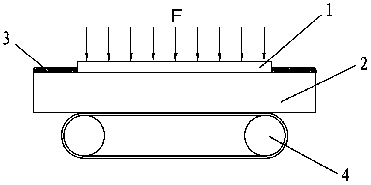
[0042] Example 2: Please refer to figure 2 Shown step 1, setting a smooth platform 2, to described smooth platform 2

[0043] Add liquid 3 to the surface to evenly distribute liquid 3 on the surface of the smooth platform;

[0044] Step 2, making the plastic flat plate 1 into shape through injection molding process;

[0045] Step 3, placing the plastic plate 1 after demoulding on the smooth platform 2;

[0046] Step 4, apply force to make the plastic plate 1 pass the vibrator 4 on the surface of the smooth platform 2 where the liquid is distributed, and vibrate

[0047] The smooth platform is moved, and the plastic plate and the smooth platform are vacuum-adsorbed by the liquid, and the force is removed;

[0048] Step 5, further cooling and shaping the vacuum-adsorbed plastic plate 1 and the smooth platform 2 .

[0049] Step 6. Remove the cooled and shaped plastic plate 1 from the smooth platform 2, and pick up the plastic plate 1.

Embodiment 3

[0050] Example 3: Please refer to figure 1 Shown step 1, setting a smooth platform 2, to described smooth platform 2

[0051] Add liquid 3 to the surface to evenly distribute liquid 3 on the surface of the smooth platform;

[0052] Step 2, making the plastic visor 1 of the photography light through injection molding process;

[0053] Step 3, placing the plastic shade 1 of the photographic light after demoulding on the smooth platform 2;

[0054] Step 4, apply force to make the plastic shading plate 1 of the photography light pass through the friction on the surface of the smooth platform 2 where the liquid is distributed.

[0055] Through the liquid 3, the plastic visor 1 of the photography light and the smooth platform 2 are vacuum-adsorbed, and the applied force is removed;

[0056] Step 5. Further cooling the plastic shading plate 1 and the smooth platform 2 of the vacuum-adsorbed photography lamp

[0057] Shaping, cooling and shaping the best time is 20min. .


PUM


Abstract

The invention provides an injection molding production process capable of reducing the warping possibility of a plastic plate. The injection molding production process comprises following steps: 1. arranging a smooth platform, adding liquid to the surface of the smooth platform, and uniformly distributing the liquid on the surface of the smooth platform; 2. molding the plastic plate through the injection molding process; 3. arranging the demoulded plastic plate on the smooth platform; 4. applying force so as to enable the plastic plate to abrade the surface of the smooth platform distributed with liquid or enable the plastic plate to vibrate the smooth platform, carrying out vacuum adsorption on the plastic plate and the smooth platform through liquid, and retracting the applied force; 5. further cooling and shaping the plastic plate and the smooth platform subjected to vacuum adsorption; and 6. separating the cooled and shaped plastic plate from the smooth platform, and picking up the plastic plate. According to the injection molding process, the process flow is simple, the use range is wide, the plastic plate only needs to be flatly attached to the smooth platform distributed with liquid; due to the utilization of the vacuum adsorption force, the possibility of warping deformation of the plastic plate in the cooling and shaping process can be reduced, and on the basis of not modifying the original matched production device of injection molding production, the yield of the plastic plate is greatly increased, the injection molding production time is shortened, and the injection molding production process has market economic benefits.

Description

technical field [0001] The invention relates to the technical field of injection molding production technology, in particular to an injection molding production technology for reducing the warpage of plastic flat plates, and is especially suitable for the production requirements of plastic light-shielding plates for photographic lamps. Background technique [0002] The existing plastic flat injection molding process mainly includes five stages of mold closing, filling, pressure holding, cooling, and demoulding, in which the design of the cooling system is very important. This is because the molded plastic product can only be cooled and solidified to a certain rigidity, and the deformation of the plastic product due to external force and internal stress relief process can be avoided after demoulding. Since the cooling time accounts for about 70% to 80% of the entire molding cycle, a well-designed cooling system can greatly shorten the molding time, improve injection molding p...

Claims


Application Information

Patent Timeline
Patent Type & Authority Patents(China)
IPC IPC(8): B29C45/00B29C45/72
CPCB29C45/0025B29C45/0053B29C45/7207B29L2007/002
Inventor 杨国麟黄清冰
Owner 莆田市多容光学电子有限公司
Why Eureka
Try Eureka