
A kind of dual-source trolleybus electricity control method

A trolleybus and electric control technology, applied in electric vehicles, electric traction, power lines, etc., can solve the problems of voltage jump, damage to the power collection system and line network, etc., to prevent voltage jump, line network internal resistance loss The effect of reducing and improving safety

Active Publication Date: 2017-04-12
ZHENGZHOU YUTONG BUS CO LTD
View PDF6 Cites 0 Cited by
  • Summary
  • Abstract
  • Description
  • Claims
  • Application Information

AI Technical Summary

Problems solved by technology

[0005] The purpose of the present invention is to provide a dual-source trolleybus electricity control method to solve the problem that the current control method causes voltage jumps and damages the power collection system and the line network due to the frequent passing of the electric car through the insulation section of the line network

Method used


Image

  • A kind of dual-source trolleybus electricity control method
  • A kind of dual-source trolleybus electricity control method
  • A kind of dual-source trolleybus electricity control method

Examples


Embodiment 1

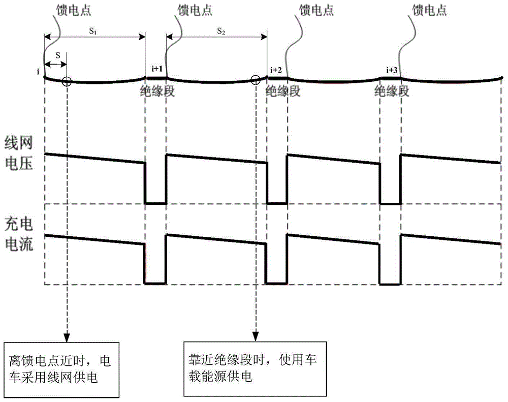
[0020] The invention provides a dual-source trolleybus electricity control method. The control principle of the method is as follows: the power supply line network of the trolleybus is divided into several operating sections, and each operating section consists of a power supply section capable of supplying power and an adjacent section The power supply section is composed of an insulating section that cannot supply power. The feed point of the power supply section is connected to the power grid through a wire. When the feed point or in the insulation section, the line network power supply is stopped, and the tram is powered by the on-board energy to achieve the purpose of actively eliminating voltage jumps.

[0021] Such as figure 1 As shown, the insulation segment i and its adjacent length are S 1 The power supply section constitutes the i-th operating interval, and the insulation section i+1 and its adjacent length are S 2 The power supply section constitutes the i+1th op...

Embodiment 2

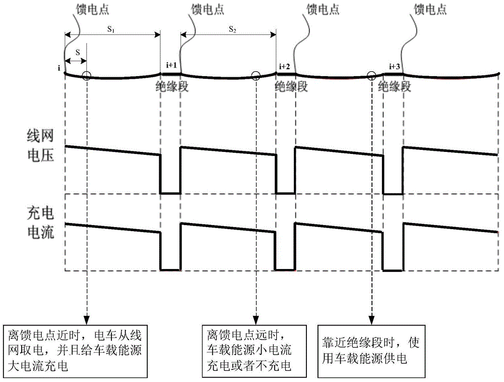
[0024] The difference between this embodiment and Embodiment 1 is that in addition to using different power sources for power supply at different positions in the operating interval, within the set distance close to the feed point, the charging current of the line network to the electric vehicle on-board energy is the same as that in the corresponding operating interval. The distance of the tram from the feed point is related: the greater the distance of the tram from the feed point, the lower the supply current.

[0025] Such as figure 2 As shown, when the tram is close to the feed point, the tram takes power from the line network in the power supply section of the running section, and at the same time, the line network charges the vehicle energy with a large current; when the distance between the tram and the feed point gradually increases, the charging The current gradually decreases; when the distance between the electric car and its nearest insulating section is reduced ...

Embodiment 3

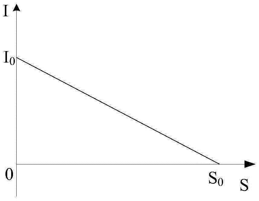
[0027] Such as image 3 As shown, in each operating interval, the charging current value of the on-board power supply decreases linearly with the increase of the distance between the tram and the feeding point of the operating interval, wherein the charging current value at the feeding point I is the maximum I 0 , with the increase of the distance S between the current collector and the feeding point of the operating range, the charging current value I decreases continuously, when S reaches the set distance S 0 When the charging current is the smallest, it can even be directly reduced to 0. According to the distance S between two insulation segments 供 And the calculated S, set up the current coefficient k (0≤k≤1) to control the charging current, that is, k=f(s,s 供 ), the charging current is adjusted according to the constant change of S, and the vehicle controller sends a control signal of the charging current to the collector controller.

[0028] Since the power supply se...


PUM


Abstract

The invention discloses a power consumption control method for a double-source trolleybus. Each operating zone consists of a power supply section and an insulating section, and feeding points of the power supply sections are connected with the power grid through wires. During operation in each operating zone, when the trolleybus is close to the corresponding feeding point, the trolleybus gets power from a wire network of the power supply section of the corresponding operating zone; when the trolleybus is away from the corresponding feeding point or in the corresponding insulating section, the trolleybus is powered by an energy source on the trolleybus. The power consumption control method for the double-source trolleybus has the advantages that by intelligent charging strategies and reasonable utilization of wire network facilities, power consumption of the whole trolleybus is controlled actively; when the trolleybus is close to the feeding points, wire networks are adopted for power supply, and when the trolleybus is away from the feeding points or in the insulating sections, the whole trolleybus is controlled to stop getting power from the wire networks, and the energy source on the trolleybus starts to supply power to the trolleybus, so that voltage jump caused by the insulating sections can be prevented effectively, arcing and impact to the wire networks can be reduced, a current collection system and the wire networks are protected from damages, wire network protection is facilitated, and system safety can be improved.

Description

technical field [0001] The invention relates to a method for controlling power consumption of a dual-source trolleybus. Background technique [0002] Pure electric buses apply electric drive technology, which meets the needs of energy conservation and environmental protection, but short driving range, large-capacity batteries and infrastructure costs of charging stations restrict their development. The trolleybus can realize the pure electric driving of the vehicle on the grid, but it is highly dependent on the wire network, and its inability to operate off the grid also restricts its development. Therefore, dual-source trackless pure electric vehicles that combine line grid energy or other energy with pure electric battery energy have attracted much attention. The dual-source trolleybus can run away from the trolleybus grid. It is driven by the on-board power supply in the section without overhead line network, and at the same time uses the on-board charger to charge the o...

Claims


Application Information

Patent Timeline
Patent Type & Authority Patents(China)
IPC IPC(8): B60M1/00B60L9/00
Inventor 李高鹏朱光海高建平曾升位跃辉秦学
Owner ZHENGZHOU YUTONG BUS CO LTD
Learn More