Lifting device for substation
A hoisting device and a substation technology, applied in the direction of cranes, etc., can solve the problems of difficult passage of substation cranes, time-consuming and labor-intensive insulating scaffolds, etc., and achieve the effects of saving manpower and material resources, increasing versatility, and improving work efficiency.
- Summary
- Abstract
- Description
- Claims
- Application Information
AI Technical Summary
Problems solved by technology
Method used
Image
Examples
Embodiment 1
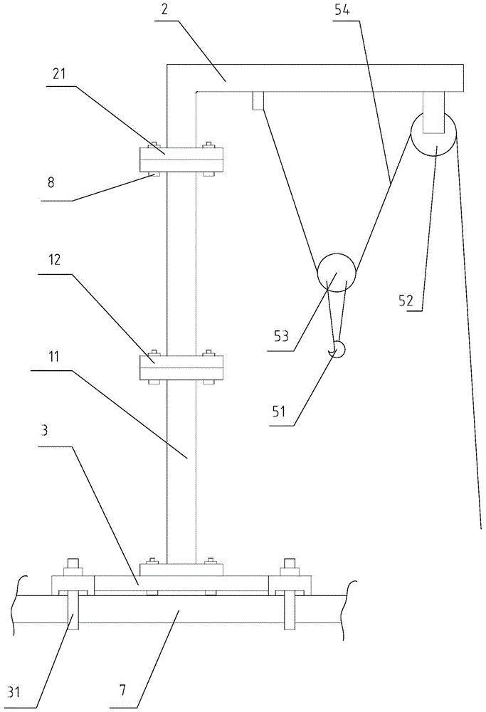
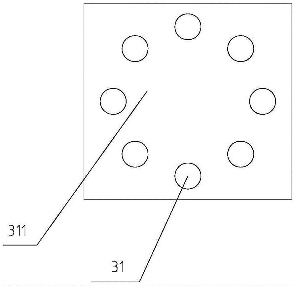
[0026] refer to figure 1 , a hoisting device for a substation shown, including a support body, the bottom of the support body is provided with a base 3, the hoisting device is fixed by connecting the base 3 to the grid support 7 in the substation, and the top of the support body is provided with a boom assembly 2 , one end of the hanging arm assembly 2 is connected with a static pulley 52 and a suspension rope 54, one end of the suspension rope 54 is fixedly connected with the suspension arm assembly 2, the suspension rope 54 is connected with a movable pulley 53, and the movable pulley 53 is provided with a suspension hook 51 , Suspender rope 54 walks around movable pulley 53 and static pulley 52 successively. The equipment that needs to be disassembled is connected by the suspension hook 51, and the other end of the suspension rope 54 is pulled by the ground personnel to lift the equipment, and the movable pulley 53 and the static pulley 52 can save physical strength.
[00...
Embodiment 2
[0032] refer to Figure 4 with Figure 5 In this embodiment, on the basis of the embodiment, a sliding sleeve 22 is provided on the connecting seat 21, and a sliding hole 221 is provided in the sliding sleeve 22 along the radial direction of the support body, and a boom 23 is installed in the sliding hole 221, and the boom 23 It can be moved along the axial direction of the sliding hole 221 to change the telescopic length, so that the hook 51 is located directly above the equipment.
[0033] Further, the boom assembly 2 also includes an inner sleeve 9 and a pressure bolt 93, the inner sleeve 9 is arranged in the sliding hole 221, the inner sleeve 9 is connected with the boom 23, and the inner circular surface of the inner sleeve 9 is along the axis of the inner sleeve 9. To be provided with slit 91, slit 91 makes the inner circle of inner sleeve 9 deformable, and the outer circular surface of inner sleeve 9 is provided with groove 92, and the inner wall of slide hole 221 is p...
Embodiment 3
[0036] Compared with Embodiment 2, this embodiment changes the connection mode of the sliding sleeve and the boom. The connecting seat is provided with a sliding sleeve, and a sliding hole is arranged in the sliding sleeve along the radial direction of the support body, and the boom is installed in the sliding hole. Sliding hole and boom thread fit. Rotate the boom, the boom can move along the axial direction of the slide hole.
PUM
 Abstract
Description
Claims
Application Information
 - R&D
- Intellectual Property
- Life Sciences
- Materials
- Tech Scout
- Unparalleled Data Quality
- Higher Quality Content
- 60% Fewer Hallucinations
Browse by: Latest US Patents, China's latest patents, Technical Efficacy Thesaurus, Application Domain, Technology Topic, Popular Technical Reports.
© 2025 PatSnap. All rights reserved.Legal|Privacy policy|Modern Slavery Act Transparency Statement|Sitemap|About US| Contact US: help@patsnap.com


