Blanking plug

A plug and sliding sleeve technology, which is applied in wellbore/well components, earthmoving, sealing/packing, etc., can solve the problems of easy blowout accidents and long plugging time, so as to prevent blowout accidents and work technology. Simple and easy to operate effect

Active Publication Date: 2015-09-02
PETROCHINA CO LTD
View PDF8 Cites 1 Cited by
  • Summary
  • Abstract
  • Description
  • Claims
  • Application Information

AI Technical Summary

Problems solved by technology

[0005] Aiming at the shortcomings of the existing technology that when unblocking after the controllable snubbing operation is completed, the downhole pressure is suppressed due to long plugging time, and blowout accidents are prone to occur

Method used


Image

  • Blanking plug
  • Blanking plug
  • Blanking plug

Examples


Embodiment Construction

[0032] The technical solutions in the embodiments of the present invention will be clearly and completely described below with reference to the accompanying drawings in the embodiments of the present invention. Obviously, the described embodiments are only a part of the embodiments of the present invention, but not all of the embodiments. Based on the embodiments of the present invention, all other embodiments obtained by those of ordinary skill in the art without creative efforts shall fall within the protection scope of the present invention.

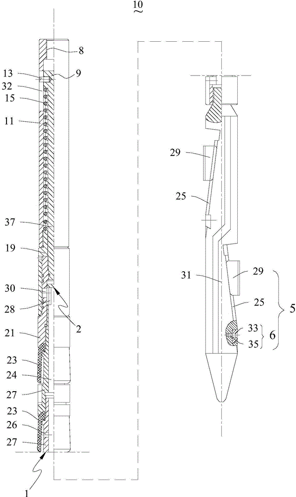
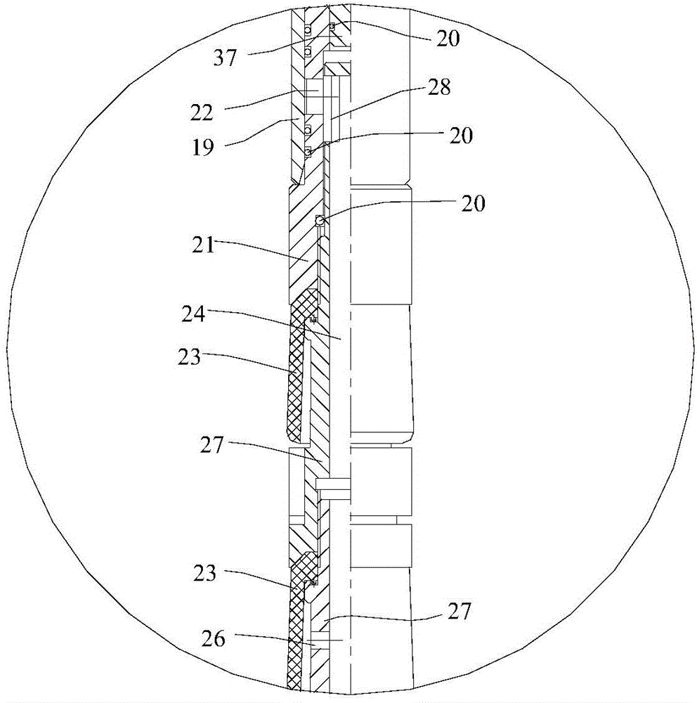
[0033] See figure 1 . The occluder 10 provided by the embodiment of the present invention includes a central tube 27 having a first end 1 and a second end 2 opposite to each other, and the central tube 27 is close to the side walls of the first end 1 and the second end 2 A liquid inlet hole 26 and a liquid outlet hole 28 are respectively penetrated through the upper part; a sealing rubber sleeve 23 is sleeved outside the central pipe...


PUM


Abstract

The invention provides a blanking plug comprising a central tube having a first end and a second end reversed to each other, a liquid inlet, a liquid outlet, a hermetic rubber sleeve and a sliding sleeve. The liquid inlet and the liquid outlet are penetratingly formed in the side walls, close to the first end and the second end, of the central tube; the central tube is nested in the hermetic rubber sleeve; the sliding sleeve is connected with the first end of the central tube in a sliding mode, and the sliding sleeve is provided with a first operating position used for blocking the liquid outlet and a second operating position used for unblocking the liquid outlet. A cavity of the blanking plug, and the liquid inlet and the liquid outlet which are communicated with the cavity form a fluid channel; the sliding sleeve is lifted to unblock the liquid outlet and allow the first operating position to switch to the second operating position; high-pressure fluid from the bottom of a well moves upward through the fluid channel to achieve decompression, and thus blowout accidents can be prevented from the source.

Description

technical field [0001] The application belongs to the technical field of oil and gas development, and in particular relates to a plug. Background technique [0002] With the development of oil and gas fields in the middle and late stages, the reservoir pressure decreases and the number of low-pressure wells increases. At present, for low-pressure wells, it is necessary to inject killing fluid to kill the well during operation to increase the reservoir pressure. Wells with serious leakage also need to take multiple killing methods to increase the reservoir pressure. However, the injection of killing fluid will pollute the oil layer and increase the oil pumping and drainage period after the operation, increase the water storage in the formation and increase the cost of sewage recycling treatment, which will bring difficulties to the recovery of the oil well after the operation. . [0003] Controlled snubbing operation refers to the use of controllable tripping sucker rod dev...

Claims


Application Information

Patent Timeline
Patent Type & Authority Applications(China)
IPC IPC(8): E21B33/12E21B23/01E21B34/06
Inventor 于雷李洪斌武雅慧惠晓永于超杜凯荆琪欧阳涛付玉红
Owner PETROCHINA CO LTD
Why Eureka
Try Eureka