
Round cutter box capable of having disc cutter replaced bidirectionally

A technology of disc-shaped hobs and circular knives, applied in mining equipment, earthwork drilling, tunnels, etc., can solve the problems of reducing the overall strength of the cutterhead, affecting the overall structure of the cutterhead, cracking of welds, etc., and shortening downtime , The overall structure design is reasonable, the effect of avoiding stress concentration

Active Publication Date: 2015-09-02
CHINA RAILWAY ENGINEERING EQUIPMENT GROUP CO LTD
View PDF9 Cites 14 Cited by
  • Summary
  • Abstract
  • Description
  • Claims
  • Application Information

AI Technical Summary

Problems solved by technology

At present, the shape of the tool box that can be used for back tool change is rectangular. The rectangular tool box is a panel structure, and stress concentration is easy to occur at the four corners of the rectangle. The overall structure of the disc; in addition, the rectangular tool box that can meet the tool change on the back has a larger size in the direction of the long side of the rectangle, which leads to a reduction in the overall strength of the cutter head when more tool boxes are arranged on the cutter head

Method used


Image

  • Round cutter box capable of having disc cutter replaced bidirectionally
  • Round cutter box capable of having disc cutter replaced bidirectionally
  • Round cutter box capable of having disc cutter replaced bidirectionally

Examples


Embodiment Construction

[0023] The specific implementation manners of the present invention will be described in detail below in conjunction with the accompanying drawings.

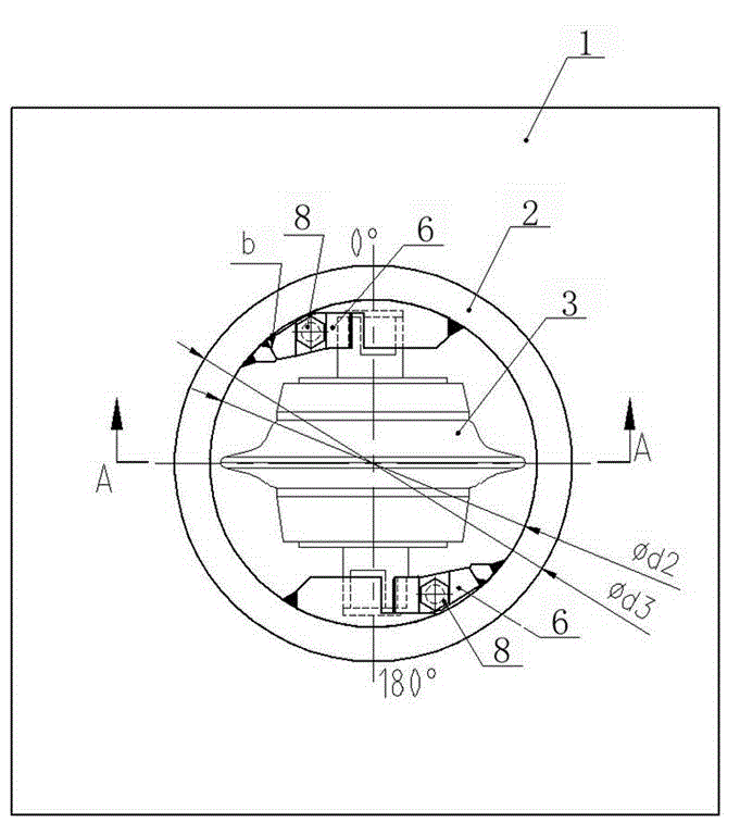
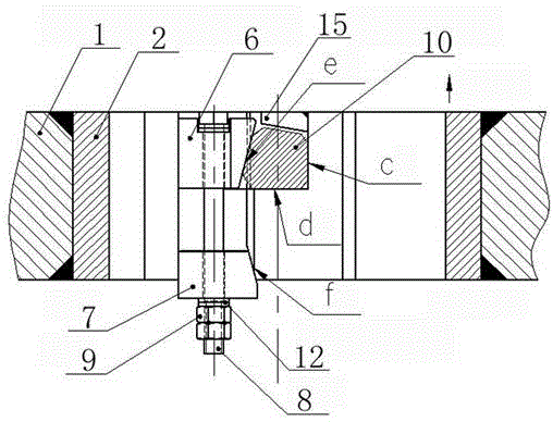
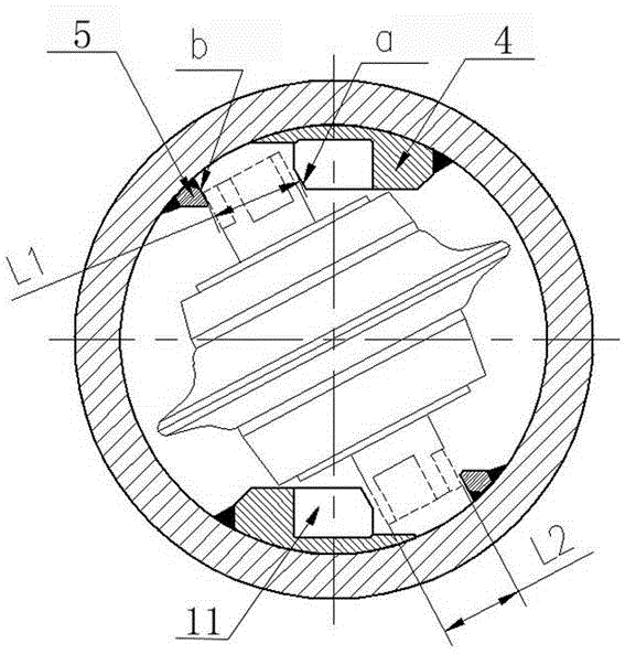
[0024] see Figure 1-Figure 4 , a circular knife box capable of bidirectionally replacing disc-shaped hobs, including a cylindrical ring-shaped knife box body fixed on the cutter head and two center-symmetric rollers arranged inside the knife box body. The cutter shaft fastening unit, the hob shaft fastening unit includes a load-bearing guide bar fixed on the inner wall of the knife box box, a limiter fixed on the inner wall of the knife box box and correspondingly set at a certain angle with the load-bearing guide bar Position guide bar, and wedge-shaped compression block, wedge-shaped tension block, tension bolt, lock washer and two nuts that are matched between the load guide bar and the limit guide bar, the load guide bar faces the limit One side of the guide bar is provided with a stepped bearing platform, the hob shaft is...


PUM


Abstract

The invention relates to the technical field of tunnel boring machine engineering machinery, in particular to a round cutter box capable of having a disc cutter replaced bidirectionally. The round cutter box capable of having the disc cutter replaced bidirectionally comprises a ringlike cutter box body and two cutter shaft fastening units, wherein the ringlike cutter box body is fixed on a cutter disc and is in a cylindrical shape, the cutter shaft fastening units are arranged at the inner side of the cutter box body and are in central symmetry, and each cutter shaft fastening unit comprises a load-bearing guide bar, a limiting guide bar, a wedge-shaped pressing block, a tensioning block, a tension bolt and nuts, wherein each load-bearing guide bar is fixed to the inner wall of the cutter box body, each limiting guide bar is fixed to the inner wall of the cutter box body and arranged in a mode that the limiting guide bar corresponds to the corresponding load-bearing guide bar and a certain included angel is formed between the limiting guide bar and the corresponding load-bearing guide bar, and each wedge-shaped pressing block, the corresponding tensioning block, the corresponding tension bolt and the corresponding nuts are arranged between the corresponding load-bearing guide bar and the corresponding limiting guide bar in a matched mode. By means of the round cutter box, the disc cutter can be replaced from either the back side or the front side of the cutter disc, the cutter is replaced from the back side in the construction process of a tunnel boring machine, the cutter is replaced from the front side in the production, assembling and debugging process of the tunnel boring machine, and the cutter box body of the round cutter box is of a round structure, so that the cutter box body on the cutter disc is made to be capable of saving the space and being subjected to even stress.

Description

technical field [0001] The invention relates to the technical field of tunnel boring machine construction machinery, in particular to a circular cutter box capable of bidirectionally replacing disc-shaped hobs. Background technique [0002] The disc-shaped hob installed on the cutter head is the main tool for excavating the tunnel of the tunnel boring machine. During the construction process of the tunnel boring machine, the hob is a wearable part and needs to be replaced frequently. There are two ways to replace the hob at present, one is to replace it at the front side of the cutter head, and the other is to replace it at the back of the cutter head. [0003] When replacing the hob in front of the cutterhead, the cutterhead of the tunnel boring machine needs to be moved back a certain distance, and personnel enter the gap between the cutterhead and the tunnel face for replacement. This kind of operation not only has the risk of face instability, but also has the disadvant...

Claims


Application Information

Patent Timeline
IPC IPC(8): E21D9/08
Inventor 李建斌刘晓恒
Owner CHINA RAILWAY ENGINEERING EQUIPMENT GROUP CO LTD
Learn More