Supercharge Your Innovation With Domain-Expert AI Agents!

Heat exchange system and heat exchanger thereof

A heat exchanger and heat exchange fin technology, applied in the field of heat exchange and multi-layer parallel flow heat exchangers, can solve the problem of reducing the heat exchange performance of the heat exchanger, discounting the heat exchange effect of liquid refrigerant, and unsatisfactory heat exchange effect, etc. problem, to achieve the effect of improving heat transfer performance

Active Publication Date: 2015-09-02
ZHEJIANG SANHUA INTELLIGENT CONTROLS CO LTD
View PDF6 Cites 6 Cited by
  • Summary
  • Abstract
  • Description
  • Claims
  • Application Information

AI Technical Summary

Problems solved by technology

[0007] In the existing multi-layer heat exchanger, when the refrigerant enters the header 5' from the header 4' and then flows from the header 5' to the header 6', it flows from top to bottom, because the header The refrigerant in the tube 5' is a mixture of gas and liquid. When the refrigerant flows downward from the header 5', the liquid refrigerant will flow downward more easily due to gravity, while the gas refrigerant will flow downward due to the gravity. It is lighter in weight and tends to move upwards. At this time, the liquid refrigerant and gaseous refrigerant will form a blockage in the header 5', resulting in poor flow and affecting heat exchange efficiency.
In addition, when the refrigerant flows from the header 5' to the header 6' from top to bottom, the liquid refrigerant may directly flow from the center of the inner cavity of the microchannel flat tube 8' due to the effect of gravity. The upper header 5' drops directly to the lower header 6'. At this time, the liquid refrigerant is not in contact with the cavity wall of the microchannel flat tube channel 8' of the heat exchanger, and the gaseous refrigerant is squeezed to the The inner cavity wall of the microchannel flat tube 8' is in contact with the microchannel flat tube channel of the heat exchanger to exchange heat with the surrounding air. When the liquid refrigerant does not contact the cavity wall of the microchannel flat tube channel, it directly falls When it reaches the lower header, the heat transfer effect of this part of the liquid refrigerant is greatly reduced, so the heat transfer effect is not ideal, which reduces the heat transfer performance of the heat exchanger

Method used


Image

  • Heat exchange system and heat exchanger thereof
  • Heat exchange system and heat exchanger thereof
  • Heat exchange system and heat exchanger thereof

Examples


Embodiment Construction

[0042] Specific embodiments of the present invention will be described below in conjunction with the accompanying drawings.

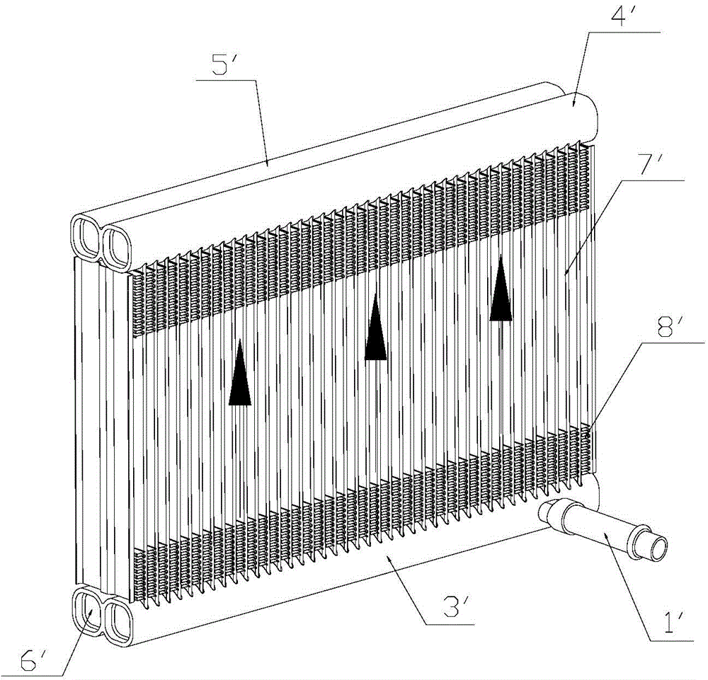
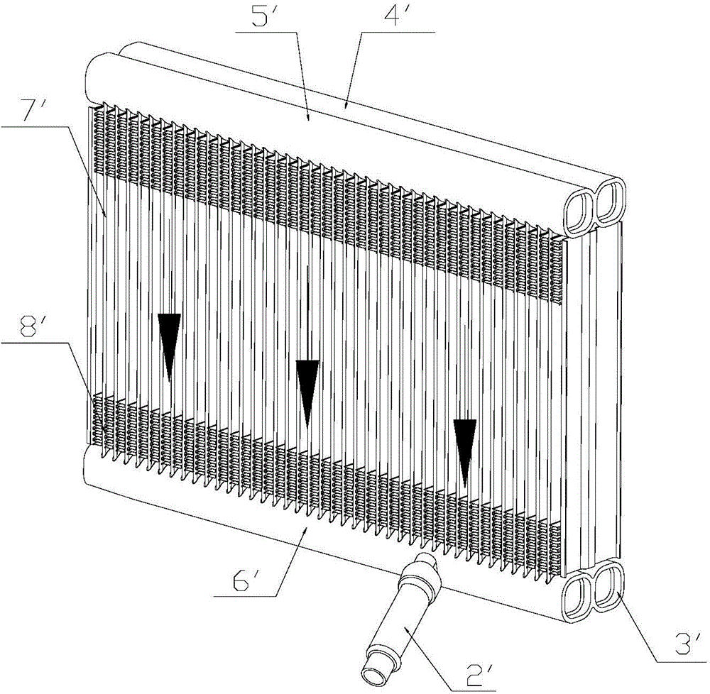
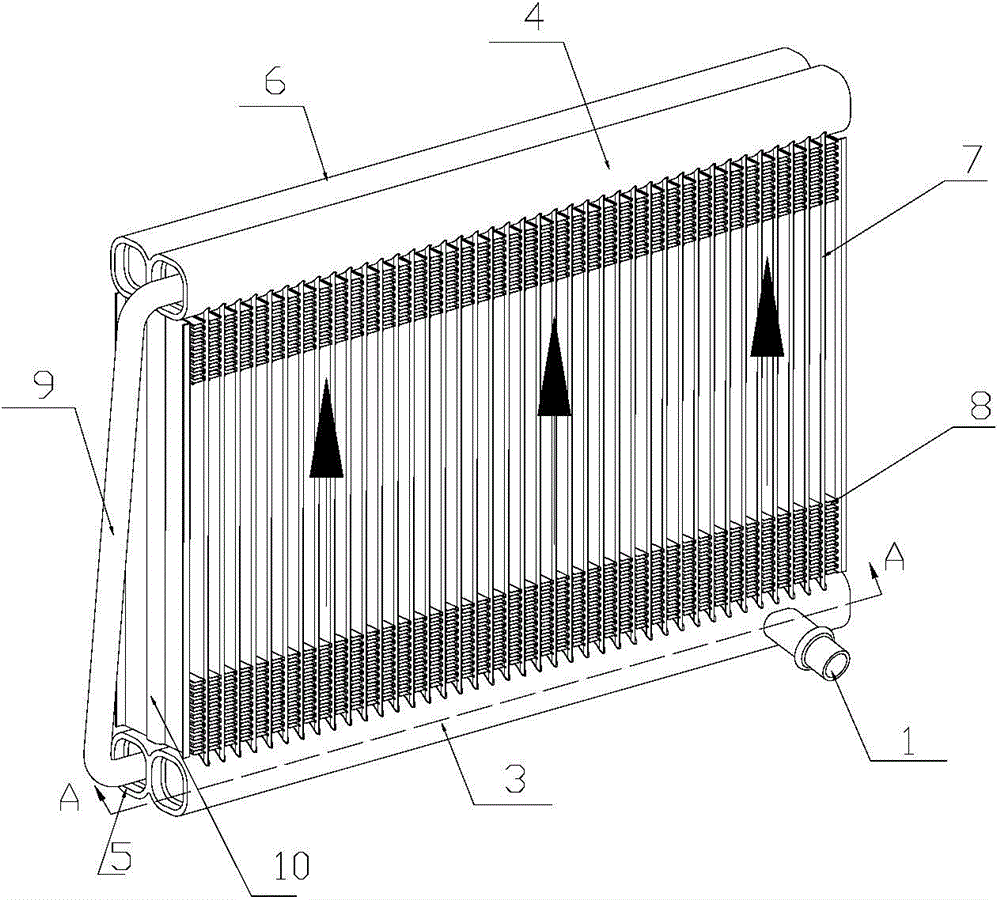
[0043] The heat exchanger of the present invention is used for refrigerant to flow in and out, and exchanges heat with the air around the heat exchanger when the refrigerant flows through the heat exchanger. see image 3 , Figure 4 and Figure 5 As shown, it shows a schematic structural diagram of the first embodiment of the heat exchanger of the present invention. in Figure 5 The refrigerant inlet pipe and refrigerant outlet pipe of the heat exchanger of the present invention are not shown in the figure. Such as Figure 3 to Figure 5 As shown, in this embodiment the heat exchanger of the present invention includes a refrigerant inlet pipe 1 , a refrigerant outlet pipe 2 and two layers of heat exchange fins between the refrigerant inlet pipe 1 and the refrigerant outlet pipe 2 . Wherein the first layer of heat exchange fins includes a lower head...


PUM


Abstract

The invention provides a heat exchanger comprises at least two layers of heat exchanger fins, each layer of heat exchanger fins comprises a lower collecting pipe, an upper collecting pipe, a plurality of microchannel flat tubes connecting the upper collecting pipe and the lower collecting pipe, and fins disposed among the microchannel flat tubes. The lower collecting pipe of the first layer of heat exchanger fins is provided with a refrigerant inlet tube, the upper collecting pipe of the last layer of heat exchanger fins is provided with a refrigerant outlet pipe, a connecting channel is disposed between an upper collecting pipe of a former layer of heat exchanger fins and a lower collecting pipe of a later layer of heat exchanger fins, a refrigerant pass through the connecting channel from the former layer of heat exchanger fins to the later layer of heat exchanger fins, and the refrigerant flows from the lower portion to the upper portion in the microchannel flat tubes of each layer of heat exchanger fins. According to the heat exchanger, the refrigerant flows from the lower portion to the upper portion in the microchannel flat tubes of each layer of heat exchanger fins, so the heat exchange performance of the heat exchanger can be raised.

Description

【Technical field】 [0001] The invention belongs to the field of heat exchange, in particular to the field of multilayer parallel flow heat exchangers. 【Background technique】 [0002] As a heat exchange device, heat exchangers are used in many fields that require heat exchange, especially in air conditioners, where heat exchangers are an important part of air conditioners. Among them, because the parallel flow heat exchanger has the characteristics of high cooling efficiency, small size, light weight, and strong pressure resistance, parallel flow heat exchangers are increasingly used in air conditioners. [0003] The parallel flow heat exchanger is mainly composed of microchannel flat tubes, cooling fins and headers. There are headers at both ends of the microchannel flat tubes for distributing and collecting refrigerant. Corrugated or louver-shaped cooling fins are arranged between adjacent microchannel flat tubes to enhance the heat exchange efficiency between the heat exc...

Claims


Application Information

Patent Timeline
Patent Type & Authority Applications(China)
IPC IPC(8): F25B39/00
CPCF25B27/00F25B29/003F25B30/02
Inventor 不公告发明人
Owner ZHEJIANG SANHUA INTELLIGENT CONTROLS CO LTD
Features
  • R&D
  • Intellectual Property
  • Life Sciences
  • Materials
  • Tech Scout
  • Unparalleled Data Quality
  • Higher Quality Content
  • 60% Fewer Hallucinations
Learn More