Fiber grating vibration sensor

A technology of vibration sensor and optical fiber grating, which is applied to instruments, measuring devices, and measuring ultrasonic/sonic/infrasonic waves, etc., can solve the problem of high fatigue life, achieve the effects of improving fatigue life, avoiding chirp, and improving reliability and stability

Active Publication Date: 2015-09-02
NUCTECH CO LTD
View PDF7 Cites 3 Cited by
  • Summary
  • Abstract
  • Description
  • Claims
  • Application Information

AI Technical Summary

Problems solved by technology

[0005] 1. Long-term installation in harsh outdoor environment, and unattended, the sensor needs to have a stable structure and high fatigue life;

Method used


Image

  • Fiber grating vibration sensor

Examples


Embodiment Construction

[0028] In order to make the purpose, structure and advantages of the present invention clearer, the present invention will be further described in detail below in conjunction with the accompanying drawings.

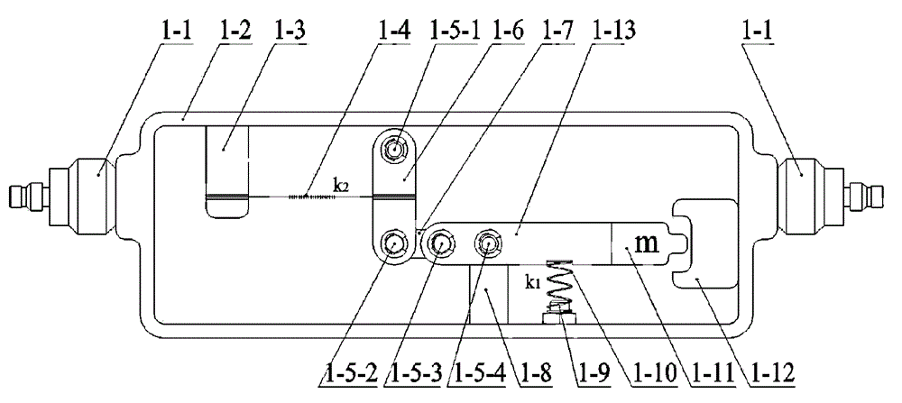
[0029] refer to figure 1 , according to one embodiment of the present invention, the fiber grating vibration sensor includes:

[0030] Support shell 1-2;

[0031] The link mechanism is located in the support housing 1-2, and the link mechanism includes a first link 1-6, a second link 1-7, a third link 1-13, a first fixed shaft 1 -5-1. The first movable shaft 1-5-2, the second movable shaft 1-5-3, and the second fixed shaft 1-5-4; wherein, the first fixed shaft 1-5-1, The rotation axis directions of the first movable rotating shaft 1-5-2, the second movable rotating shaft 1-5-3, and the second fixed rotating shaft 1-5-4 are parallel to each other and perpendicular to the length direction of the strained fiber grating 1-4; The first fixed rotating shaft 1-5-1 and the sec...


PUM


Abstract

A fiber grating vibration sensor comprises a support housing (12) and a connection rod mechanism disposed in the support housing (12). The connection rod mechanism comprises a first arm (150) in a horizontal direction and a second arm (160) in a vertical direction. A first end of the first arm (150) is a free end. A second end of the first arm (150) is connected to a second end of the second arm (160), so that the first arm (150) and the second arm (160) form an L shape. The connection rod mechanism is also provided with a first fixed rotary shaft (156). The first fixed rotary shaft (156) is perpendicular to the length direction of a strain fiber grating (120) and is fixed to the support housing (12), so that the first arm (150) can rotate relative to the first fixed rotary shaft (156), and the first arm (150) drives the second arm (160) to rotate. A first end of the strain fiber grating (120) is packaged on the second arm (160) of the connection rod mechanism, and a second end of the strain fiber grating (120) is packaged on the support housing (12). An overload protection apparatus (112) is fixed on the inner side of the support housing (12), and is used for defining a movement range of the first arm (150). The sensor can avoid a shear force in a traverse direction of the fiber grating and improve the reliability and the stability of the sensor.

Description

technical field [0001] The invention relates to an optical fiber grating vibration sensor, in particular to an optical fiber grating low-frequency vibration sensor which can be used for warning and monitoring dangerous rockfall along railway lines. Background technique [0002] Fiber Bragg grating sensing technology has been widely used in the protection and early warning of high and steep slopes due to its advantages of no electromagnetic interference, no need for power supply on site, good long-term reliability and stability, and long transmission distance. Rockfall alarm monitoring is a branch of high and steep slope protection monitoring. If dangerous rockfall can be detected in advance, the economic losses caused by dangerous rockfall to railways and highways will be greatly reduced. [0003] Some domestic universities or enterprises have carried out research on fiber grating vibration sensors or fiber grating accelerometers, most of which are cantilever beam structures...

Claims


Application Information

Patent Timeline
Patent Type & Authority Applications(China)
IPC IPC(8): G01H9/00
CPCG01H9/004
Inventor 许明毛献辉张植俊刘云飞曹学光翟江兰于国瑞耿振姜婷康凯刘单
Owner NUCTECH CO LTD
Why Eureka
Try Eureka