Automatic-limiting disconnecting link lock of switch cabinet

An automatic limit and switch technology, applied in electrical switches, electrical components, circuits, etc., can solve problems such as empty travel, easy aging and rusting of locks, and easy jamming of keys.

Inactive Publication Date: 2015-09-02
朱子毅
View PDF8 Cites 3 Cited by
  • Summary
  • Abstract
  • Description
  • Claims
  • Application Information

AI Technical Summary

Problems solved by technology

Purely mechanical locks have fixed programs and inflexible operation, and can only adopt a fixed operation mode. The locks are prone to aging and rust, and the keys are easy to jam. The microcomputer padlock is in the form of a...

Method used


Image

  • Automatic-limiting disconnecting link lock of switch cabinet
  • Automatic-limiting disconnecting link lock of switch cabinet
  • Automatic-limiting disconnecting link lock of switch cabinet

Examples


Embodiment Construction

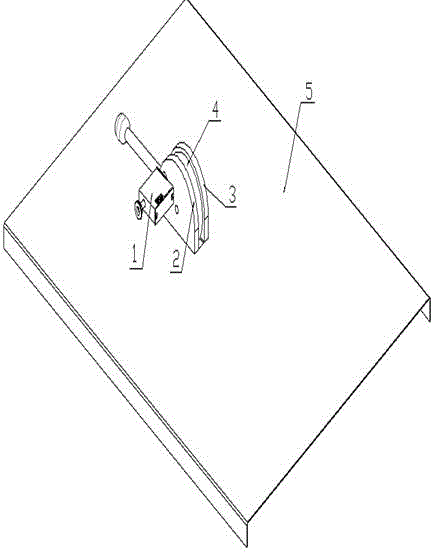
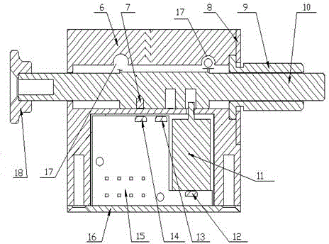
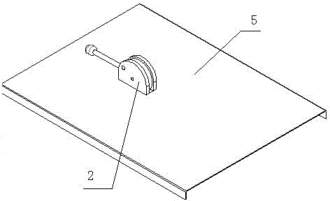
[0013] As shown in the figure, an automatic limit switch cabinet knife lock includes a housing 6 and a lock shaft 10. The lock shaft 10 is pulled in the lock shaft hole provided by the housing 6. The lock shaft 10 is provided with marbles. , the shaft hole is provided with two bead holes 17 adapted to marbles, the lock shaft 10 is inlaid with a magnet 7, and the side wall of the lock shaft hole is provided with a Hall element that senses the magnet 7; the lock shaft 10 is provided with a pin hole, and the electromagnet 7 corresponding to the pin hole is provided with an elastic mandrel; the computer key controls the pop-up and pull-back of the elastic mandrel through the signal sent by the Hall element, and the Hall element is connected to the magnet 7. Align to detect the pulling position of the lock shaft 10, the side wall of the lock shaft hole is provided with 2 Halls, the lock shaft 10 is provided with 2 pin holes, and the electromagnet 7 is also provided with 1 Hall. ...


PUM


Abstract

Disclosed in the invention is an automatic-limiting disconnecting link lock of a switch cabinet. The lock comprises a housing and a lock shaft; and the lock shaft is drawn and pulled in a lock shaft hole formed in the housing. The lock is characterized in that a hoodle is arranged at the lock shaft; and two holes matching the hoodle are formed in the housing. A magnet is embedded into the lock shaft; and hall elements sensing the magnet are arranged at the side wall of the lock shaft hole. Pin holes are formed in the lock shaft; and an elastic mandrel is arranged an electromagnet corresponding to the pin holes. A computer key controls the popping and pulling back of the elastic mandrel based on signals transmitted by the hall elements. With the lock, an accident of loaded disconnecting link pulling can be prevented; and thus accidental power failure of the client can be avoided and the economic loss can be prevented.

Description

technical field [0001] The invention relates to the field of safety operation limiting devices for power distribution cabinets in the electric power industry, in particular to an automatic limit switch cabinet knife lock. Background technique [0002] At present, the locks used in most power switch cabinet latch locks on the market are divided into pure mechanical type and microcomputer padlock type. Purely mechanical locks have fixed programs and inflexible operation, and can only adopt a fixed operation mode. The locks are prone to aging and rust, and the keys are easy to jam. The microcomputer padlock is in the form of a computer simulation operation process, downloading the operation ticket, on-site operation, and the system is easy to operate. It is flexible, but the lock is not fixedly installed, and it is easy to hang the wrong interval or miss the stroke. Contents of the invention [0003] The object of the present invention is to provide an automatic l...

Claims


Application Information

Patent Timeline
IPC IPC(8): H01H9/20H01H21/54
CPCH01H9/20H01H21/54
Inventor 朱子毅
Owner 朱子毅
Why Eureka
Try Eureka