Electrical connector

A technology of electrical connectors and connection holes, which is applied in the field of electrical connectors and can solve problems such as loosening of the shielding layer

Inactive Publication Date: 2015-09-02
CHINA AVIATION OPTICAL-ELECTRICAL TECH CO LTD
View PDF5 Cites 2 Cited by
  • Summary
  • Abstract
  • Description
  • Claims
  • Application Information

AI Technical Summary

Problems solved by technology

[0003] The purpose of the present invention is to provide an electrical connector to solve the problem in the prior art that the shielding layer is easily loosened due to vibration due to the rigid compression of the shielding ring and the pressing ring on the shielding layer

Method used


Image

  • Electrical connector
  • Electrical connector
  • Electrical connector

Examples


Embodiment Construction

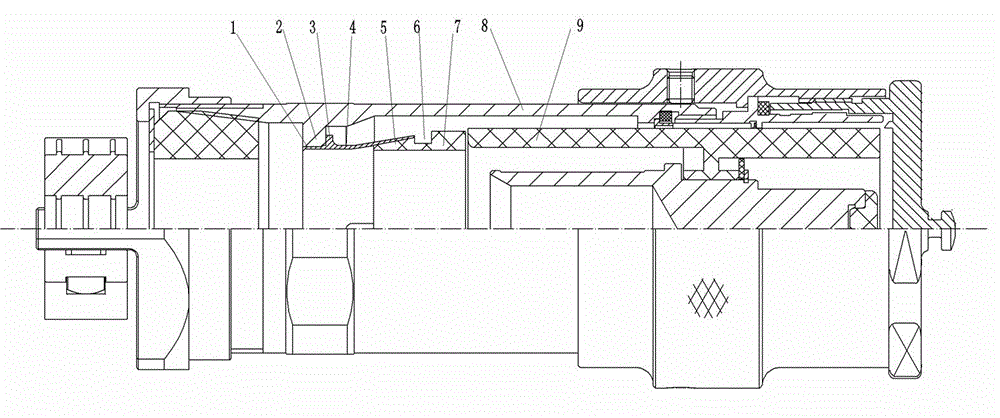
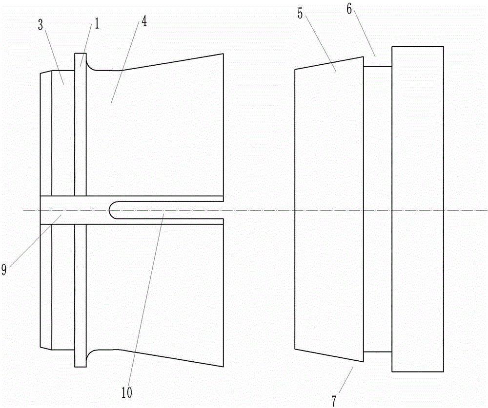
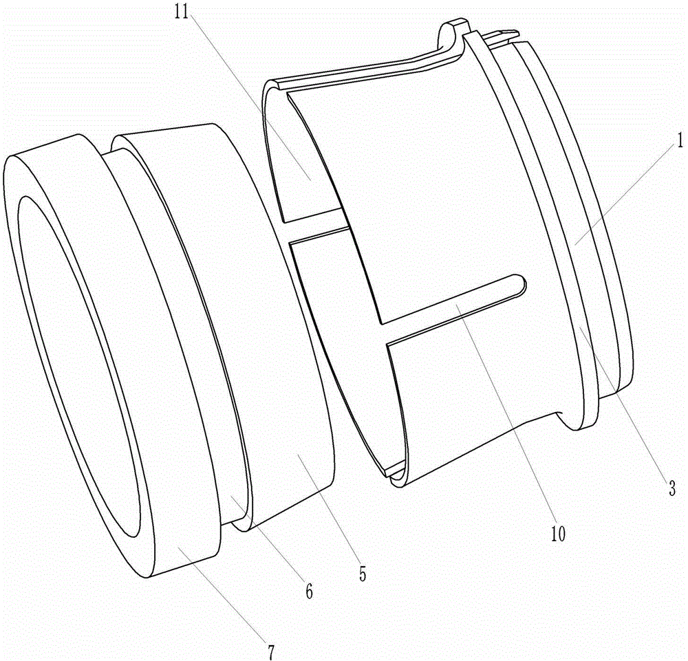
[0014] Examples of electrical connectors Figure 1~5 Shown: includes a housing 8 with a plug-in end at the front end and a shielding assembly arranged in the housing. The shielding assembly includes a shielding ring 4 and a compression ring 7. The shielding ring 4 includes an axis that is in contact with the housing and extends in the front-rear direction. The shielding ring body, the compression ring 7 includes a compression ring body whose axis extends in the front-to-back direction. The inner hole of the shielding ring body has a shielding wire connection hole section 11 at the front end, and the shielding wire connection hole section 11 gradually increases in diameter from back to front. In this embodiment, the shielding wire connection hole section 11 is tapered, and the hole wall of the shielding wire connection hole section is circumferentially spaced with three front ends extending in the front and rear directions extending to the front end of the shield ring body The c...


PUM


Abstract

The invention relates to an electrical connector. The electrical connector includes a shielding assembly having a shielding ring, the shielding ring includes a shielding ring body whose axis extends along a front-back direction, the front end of an inner hole of the shielding ring body has a shielded wire connecting hole segment for insertion of a rear end wire pressing segment on a corresponding hold-down ring in an anastomotic manner from front to back to be in contact connection with a corresponding shielded wire, the shielded wire connecting hole segment is of a flaring structure whose caliber gradually largens from back to front, and at least two wire pressing deformation grooves whose lengths extend along a front-back direction and front ends extend to a front end face of the shielding ring body are arranged at an interval along a circumferential direction on a hole wall of the shielded wire connecting hole segment. The electrical connector provided by the invention solves the problem in the prior art that the hold-down ring cannot elastically press a shielding layer.

Description

Technical field [0001] The present invention relates to an electrical connector for electrical signal transmission. Background technique [0002] For electrical connectors, it is necessary to connect the shielding layer of the cable to the housing of the electrical connector to realize the shielding of the cable. The existing common shielding methods mainly consist of two forms: outside the housing and inside the housing. The structure connected to the outside of the shell is to connect the shielding layer connector to the tail attachment of the electrical connector or the terminal post reserved on the shell. This form is not suitable for outdoor use or other harsh environments. The structure connected inside the shell mostly adopts the form of a shield ring and a compression ring. The shield ring is connected to the shell, and the shield layer of the cable is compressed and fixed between the compression ring and the shield ring. The shell is electrically connected. The problem ...

Claims


Application Information

Patent Timeline
IPC IPC(8): H01R13/648H01R4/48H01R4/50
CPCH01R4/48H01R4/5016H01R13/648
Inventor 王超
Owner CHINA AVIATION OPTICAL-ELECTRICAL TECH CO LTD
Why Eureka
Try Eureka