Low-voltage AC distribution cabinet body

A low-voltage power distribution, cabinet technology, applied in electrical components, substation/switch layout details, substation/switchgear cooling/ventilation, etc. The effect of cost, reducing the overall weight, and convenient installation and disassembly

Active Publication Date: 2015-09-02
JIANGSU JIANGCHENG ELECTRIC
View PDF8 Cites 0 Cited by
  • Summary
  • Abstract
  • Description
  • Claims
  • Application Information

AI Technical Summary

Problems solved by technology

The electrical components and lines in the existing power distribution cabinet are in good contact and reliable connection, but because the electrical components will generate a lot of heat when they work, and the heat dissipation effect of the power distribution cabinet is not ideal, the connection ends of some electrical components and lines The head is more prone to local heating, resulting in excessive local temperature, and even heating and burning, which ultimately affects the normal use of the entire power distribution cabinet
[0003] At present, the heat dissipation of the power distribution cabinet is mainly formed by directly embossing the cabinet body to form a louver-shaped heat dissipation window. There will be a space between each embossing. The exhausted hot air bounces back into the cabinet, thus weakening the working efficiency of the exhaust fan and reducing the overall heat dissipation performance of the outdoor equipment box
In addition, the heat dissipation air duct of the power distribution cabinet is unreasonable, the ventilation hole is too small, the heat dissipation area is small, the ambient temperature inside the cabinet rises rapidly, and the operation of the equipment is unstable, which may easily cause short circuits and damage to related electronic components or parts
[0004] At the same time, during use, some blades are easy to corrode and wear. In the past, the entire cabinet was generally replaced. The cost is high, the transportation and installation are very inconvenient, and the project period is long, which directly affects the quality of production and life.

Method used


Image

  • Low-voltage AC distribution cabinet body
  • Low-voltage AC distribution cabinet body
  • Low-voltage AC distribution cabinet body

Examples


Embodiment Construction

[0021] The present invention will be further described below in conjunction with the accompanying drawings.

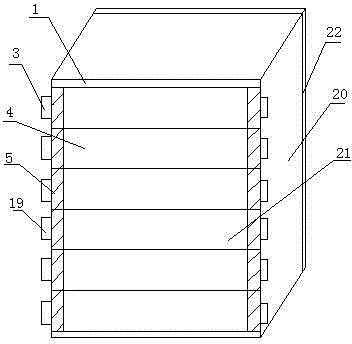
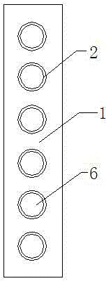
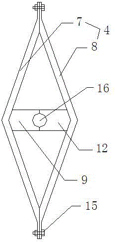
[0022] As shown in the figure, a low-voltage power distribution AC cabinet body includes a cabinet body frame 20, and a cabinet door 22 and a heat dissipation door 21 are oppositely provided on the cabinet body frame 20. The heat dissipation door 21 includes a door body 1 and a shaft sleeve 2 , the blade shaft 3, the blade 4 and the fixed casing 5, the door body 1 is a rectangular frame structure, and the two sides of the door body 1 are evenly provided with 6 fixing holes 6, and the shaft sleeve 2 is fixed on the Inside the fixing hole 6; the blade 4 includes a first blade 7 and a second blade 8, the first blade 7 and the second blade 8 are rectangular profiles bent outward from the center, and the first blade 7 The cross-sectional shape of the second blade 8 is an isosceles triangle, and a first support member 9 is provided at the bend of the first blade 7. The botto...


PUM


Abstract

The invention relates to a low-voltage AC distribution cabinet body comprising a cabinet framework. A cabinet door and a heat-dissipating door are arranged oppositely on the cabinet framework. The heat-dissipating door comprises a door body, shaft sleeves, blade rotating shafts, blades, and fixed sleeve housings. The blades comprise a first blade and a second blade which adhere to each other and which are fixed by a bolt to form a blade body. Each blade rotating shaft successively passes through the shaft sleeve on a side of the door body, the blades, and the shaft sleeve on the other side of the door body, and is fixed to the door body through a rotating wheel. The low-voltage AC distribution cabinet body is easy to install and uninstall. The weight of the blades is reduced so as to greatly contribute to constructors. Further, good flexibility and adaptability are achieved; a construction progress is accelerated; and cost is saved.

Description

technical field [0001] The invention relates to a cabinet body, in particular to a low-voltage power distribution AC cabinet body. Background technique [0002] In the power system, the power distribution cabinet is an important control and protection device, and the contact characteristics of the conductive connections in the power distribution cabinet will directly affect the reliability of the power distribution cabinet. The electrical components and lines in the existing power distribution cabinet are in good contact and reliable connection, but because the electrical components will generate a lot of heat when they work, and the heat dissipation effect of the power distribution cabinet is not ideal, the connection ends of some electrical components and lines The head is relatively easy to generate heat locally, causing the local temperature to be too high, and even generate heat and burnout, which ultimately affects the normal use of the entire power distribution cabine...

Claims


Application Information

Patent Timeline
Patent Type & Authority Applications(China)
IPC IPC(8): H02B1/56
CPCH02B1/565
Inventor 解良洪
Owner JIANGSU JIANGCHENG ELECTRIC
Why Eureka
Try Eureka