Optical signal-to-noise ratio monitoring method and device thereof

An optical signal-to-noise ratio and monitoring device technology, which is applied in transmission monitoring/testing/fault measurement systems, electromagnetic wave transmission systems, electrical components, etc., and can solve problems such as reduced transmission data quality

Inactive Publication Date: 2015-09-02
NAT UNIV OF SINGAPORE SUZHOU RES INST +1
View PDF0 Cites 14 Cited by
  • Summary
  • Abstract
  • Description
  • Claims
  • Application Information

AI Technical Summary

Problems solved by technology

The existing in-band noise monitoring method is to monitor the optical signal-to-noise ratio based on the pilot frequency monitoring technology. However, this method needs to modify the transmitter and will be affected by other factors. Interference with the data signal will cause Reduced quality of transmitted data

Method used


Image

  • Optical signal-to-noise ratio monitoring method and device thereof
  • Optical signal-to-noise ratio monitoring method and device thereof
  • Optical signal-to-noise ratio monitoring method and device thereof

Examples


Embodiment Construction

[0018] In order to make the object, technical solution and advantages of the present invention clearer, the present invention will be further described in detail below in conjunction with the accompanying drawings and embodiments. It should be understood that the specific embodiments described here are only used to explain the present invention, and do not limit the protection scope of the present invention.

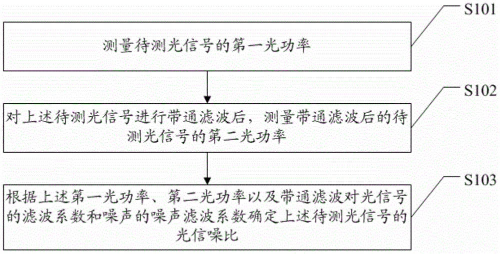
[0019] figure 1 A schematic flowchart of an embodiment of the method for monitoring the optical signal-to-noise ratio of the present invention is shown in . Such as figure 1 As shown, the method in this embodiment includes steps:

[0020] Step S101: measuring the first optical power of the optical signal to be measured;

[0021] Step S102: After band-pass filtering the above-mentioned optical signal to be measured, measure the second optical power of the optical signal to be measured after band-pass filtering;

[0022] Step S103: Determine the optical signal-to-noise...


PUM


Abstract

The invention provides an optical signal-to-noise ratio monitoring method and a device thereof. The method comprises the steps of measuring the first optical power of a to-be-monitored optical signal; after bandpass filtering is performed on the to-be-monitored optical signal, measuring the second optical power of the to-be-monitored optical signal after bandpass filtering; and determining the signal-to-noise ratio of the to-be-monitored optical signal according to the first optical power, the second optical power, the filtering coefficient of bandpass filtering to the optical signal and the filtering coefficient of bandpass filtering to the noise. The optical signal-to-noise ratio monitoring method and the device realize optical signal-to-noise ratio monitoring of the received optical signal without modification of a transmitter or data transmission influence and without affecting data transmission.

Description

technical field [0001] The invention relates to the technical field of optical fiber transmission, in particular to an optical signal-to-noise ratio monitoring method and an optical signal-to-noise ratio monitoring device. Background technique [0002] With the increasing amount of communication data on the Internet, the optical fiber transmission network is entering the era of high spectrum utilization, narrow channel spacing, long-distance transmission, high bit rate and transparent switching. However, the high-speed and dynamic transmission system in the new era has brought many new challenges to network management. Therefore, optical performance monitoring that can be used to assist optical network management begins to attract more and more people's attention. Among the many monitoring parameters, Optical Signal-to-Noise Ratio (OSNR) monitoring is the most urgent to realize. This is because the optical signal-to-noise ratio directly affects the bit error rate of the tr...

Claims


Application Information

Patent Timeline
Patent Type & Authority Applications(China)
IPC IPC(8): H04B10/07H04B10/079
Inventor 余长源余毅徐伟
Owner NAT UNIV OF SINGAPORE SUZHOU RES INST
Why Eureka
Try Eureka