A lifting type communication chassis

A communication chassis and rack technology, applied in the direction of electrical equipment shell/cabinet/drawer, electrical components, etc., can solve the problems of damage to internal communication equipment, difficult to deal with water accumulation, impossible to achieve complete sealing, etc. Water problem, achieve waterproof protection, avoid the effect of external environment damage

Active Publication Date: 2017-12-29
SUZHOU RUIQI ELECTRONICS
View PDF8 Cites 0 Cited by
  • Summary
  • Abstract
  • Description
  • Claims
  • Application Information

AI Technical Summary

Problems solved by technology

[0005] It can be seen from the above prior art that the existing communication boxes are improved and innovated in terms of structure and function to ensure the normal operation of their internal communication equipment, but with the actual application of the communication box, it can be found that the existing There are still unsatisfactory places in the communication chassis. As we all know, the selection of the setting position of the communication chassis is mainly based on the coverage area of ​​the communication network between each communication chassis. Therefore, the setting of the communication chassis position can be said to be necessary. The communication box should be adapted to the location where it is set, especially in some narrow spaces. However, the doors of the existing communication boxes are all set on the side of the box, which undoubtedly puts forward requirements for the location of the communication box. There is enough space for the rotation of the door; in addition, due to the design of the door on the side, in addition, it is impossible to achieve a complete seal between the upper door and the door frame of the existing communication box, so this kind of structure is difficult. In the case of water accumulation, there will be situations where water will soak into the communication chassis, which may cause damage to its internal communication equipment

Method used


Image

  • A lifting type communication chassis

Examples


Embodiment Construction

[0018] The specific implementation manners of the present invention will be further described in detail below in conjunction with the accompanying drawings.

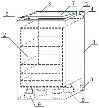
[0019] Such as figure 1 As shown, the present invention designs a lift-type communication case, including a communication case body 1, and an equipment rack 2 and a power supply module 3 arranged in the communication case body 1, and the power supply module 3 is connected to an external power supply for taking power; It includes a cover plate 7, a control module, and a control button 4, a rotating motor 5, and a lifting motor unit respectively connected to the control module; wherein, the control button 4 is arranged on the outer surface of the communication case body 1; the bottom of the communication case body 1 It is fully enclosed with all side walls, and only the top of the communication case body 1 is provided with an opening 6 to communicate with the inside and outside of the communication case body 1, and the siz...


PUM


Abstract

The invention relates to a lifting type communication case, which comprises a communication case body, an equipment rack and a power supply module, wherein the equipment rack and the power supply module are arranged in the communication case body, and the power supply module is connected to an external power supply so as to take power. The lifting type communication case is characterized by further comprising a cover plate, a control module, a control button, a rotating motor and a lifting motor unit, wherein the control button, the rotating motor and the lifting motor unit are connected with the control module, and the lifting motor unit comprises at least three electrically controlled telescopic rod motors. Based on the technical scheme designed by the invention, connection setting is carried out in allusion to the hardware modules so as to form the lifting type communication case, thereby not only being capable of effectively coping with requirements of a narrow setting position, but also being capable of effectively coping with a problem of water accumulation, truly preventing accumulated water from intruding into the internal part of the communication case body, and realizing waterproof protection for communication equipment to the maximum degree.

Description

technical field [0001] The invention relates to a lift-type communication case, which belongs to the technical field of communication equipment. Background technique [0002] With the development of the mobile communication industry, people's daily life is increasingly dependent on mobile communication, especially the use of mobile phones must rely on the coverage of mobile communication networks; operators set up communication base stations in cities, villages, or remote areas. Tower or communication chassis, using its communication equipment to cover the communication network to the communication area, to meet people's use of the mobile communication network, the communication chassis is widely used in the streets and alleys of the city based on its advantages of small size, convenient installation and easy maintenance. With the wide application of the communication case, designers and manufacturers have made many improvements and innovations for the communication case, su...

Claims


Application Information

Patent Timeline
Patent Type & Authority Patents(China)
IPC IPC(8): H05K5/00
Inventor 徐静
Owner SUZHOU RUIQI ELECTRONICS
Why Eureka
Try Eureka