
A water tank mechanism with a water blocking structure and a steam oven using the same

A water-retaining structure and technology for steaming ovens, which are applied in the field of steaming ovens, can solve problems such as water leakage, squeezing and collision interfaces, and control circuit board water inflow short-circuits, etc., to solve high sealing requirements, improve use safety, and avoid moisture short-circuits. Effect

Active Publication Date: 2022-02-11
YUNMI HULIAN TECH (GUANGDONG) CO LTD
View PDF0 Cites 0 Cited by
  • Summary
  • Abstract
  • Description
  • Claims
  • Application Information

AI Technical Summary

Problems solved by technology

The existing problem is: because the interface between the water tank seat and the water box body is often separated and closed, it is easy to squeeze and collide, resulting in the problem of water leakage at the interface, resulting in high sealing requirements for the water tank structure
At the same time, due to the lack of water retaining components, when the water tank structure leaks, it is easy to cause a short circuit of water in the control circuit board inside the steam oven, which affects the safety of the steam oven

Method used


Image

  • A water tank mechanism with a water blocking structure and a steam oven using the same
  • A water tank mechanism with a water blocking structure and a steam oven using the same
  • A water tank mechanism with a water blocking structure and a steam oven using the same

Examples


Embodiment Construction

[0028] In describing the present invention, it should be understood that the terms "longitudinal", "transverse", "upper", "lower", "front", "rear", "left", "right", "vertical", " The orientations or positional relationships indicated by "horizontal", "top", "bottom", "inner", "outer", etc. are based on the orientations or positional relationships shown in the drawings, and are only for the convenience of describing the present invention and simplifying the description, rather than Nothing indicating or implying that a referenced device or element must have a particular orientation, be constructed, and operate in a particular orientation should therefore not be construed as limiting the invention.

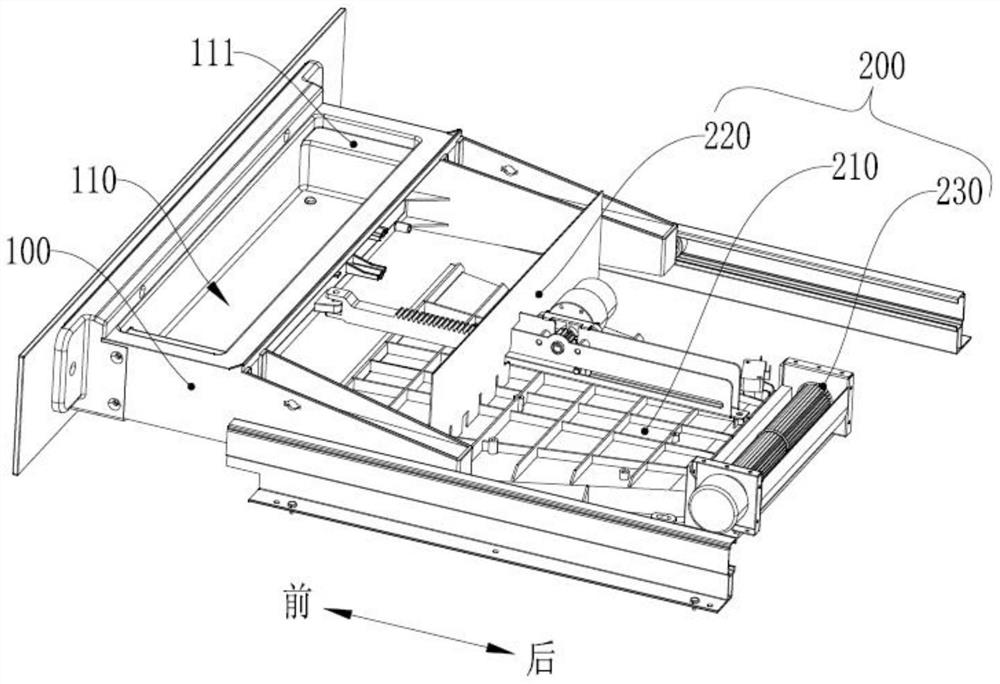
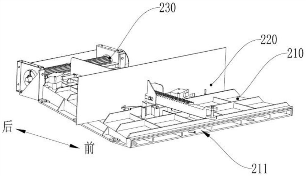
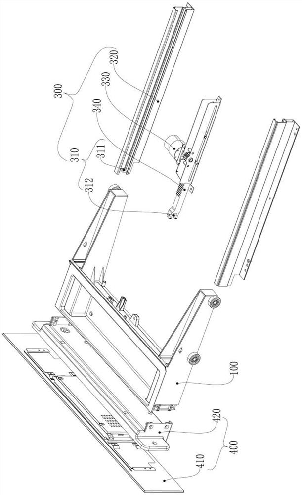
[0029] Such as Figure 1-4 As shown, 1 of this embodiment, a water tank mechanism with a water retaining structure, including a water tank body 100 and a water retaining assembly 200; the water tank body 100 has a water storage tank 110, and the water storage tank 110 is relatively ...


PUM


Abstract

The invention discloses a water tank mechanism with a water retaining structure and a steam oven using the same, which belongs to the field of household kitchen appliances. By erecting the water baffle on the heat-insulating floor frame, when the water tank body is arranged on the front side of the water baffle, the water baffle can block the water source shaking from the water storage tank, avoiding water splashing to the control circuit board, Realize the waterproof protection of the control circuit board. Through the cross-flow fan, a forward-flowing airflow is formed at the bottom of the heat-insulating floor frame. The airflow passes through the air duct to concentrate the heat of the heat-insulating floor frame forward, and realizes the moisture that is blocked by the water barrier and falls on the heat-insulating floor frame. Heating and evaporating, at the same time, the cross-flow fan also forms a forward-flowing airflow on the top of the heat-insulating floor frame, so that the water vapor flows forward, so as to prevent water vapor from flowing from the gap on the front side of the water baffle to the bottom of the water baffle. The rear side realizes waterproof protection for the control circuit board, so as to prevent the control circuit board from being damp and short-circuited and improve the safety of the steam oven.

Description

technical field [0001] The invention relates to the field of household kitchen appliances, in particular to a water tank mechanism with a water-retaining structure and a steam oven using the same. Background technique [0002] With the continuous improvement of people's quality of life, kitchen appliances are becoming more and more abundant, and ovens, steamers, etc. have gradually become necessary kitchen appliances for family life. These kitchen appliances not only have a single function, each product needs to occupy a certain amount of kitchen space, but also cost a lot to purchase separately. [0003] In order to effectively utilize the kitchen space and reduce purchase costs, at present, a steam oven has been disclosed in the prior art, which is an all-in-one machine that integrates the functions of the steam box and the oven. By placing a water tank in the original oven, using a water pump to guide the water in the water tank to the heating plate for heating and evapo...

Claims


Application Information

Patent Timeline
Patent Type & Authority Patents(China)
IPC IPC(8): A47J36/00A47J27/04A47J37/06
CPCA47J36/00A47J27/04A47J37/0664A47J2027/043
Inventor 陈小平张明王成
Owner YUNMI HULIAN TECH (GUANGDONG) CO LTD
Learn More