Novel capacitor cabinet

A capacitor cabinet, a new type of technology, is applied in electrical components, substation/distribution device enclosures, substation/switch layout details, etc. The effect of prolonging the service life and wide application range

Pending Publication Date: 2021-12-24
江苏晟海电气有限公司
View PDF0 Cites 0 Cited by
  • Summary
  • Abstract
  • Description
  • Claims
  • Application Information

AI Technical Summary

Problems solved by technology

[0003] However, the electronic components in the current capacitor cabinet will generate a lot of heat during operation, and the existing capacitor cabinet cannot effectively dissipate heat and cool down the interior. Once the temperature exceeds the load, the electronic components in the electrical cabinet will burn out due to the accumulated temperature. There may even be a phenomenon of spontaneous combustion, which poses a safety hazard; moreover, capacitor cabinets installed outdoors usually do not have rainproof performance. The carrying plate used to place electronic components inside the cabinet is generally welded and fixed, and its height cannot be adjusted, so it cannot be applied to different types of electronic components. The applicability is low, and because the carrying plate is fixed and welded, it is inconvenient Overhaul and replace the electronic components fixed above it

Method used


Image

  • Novel capacitor cabinet
  • Novel capacitor cabinet
  • Novel capacitor cabinet

Examples


Embodiment Construction

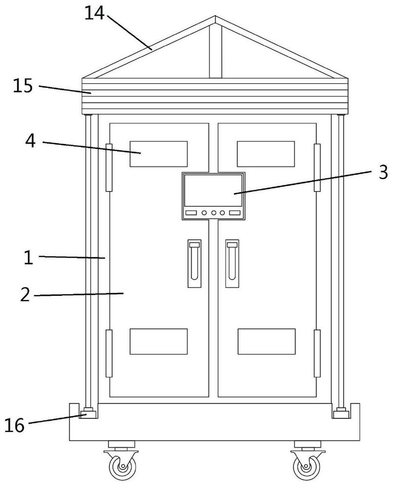
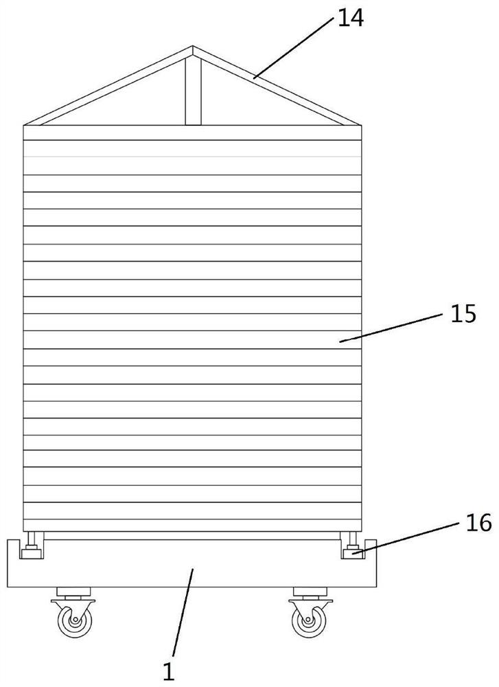
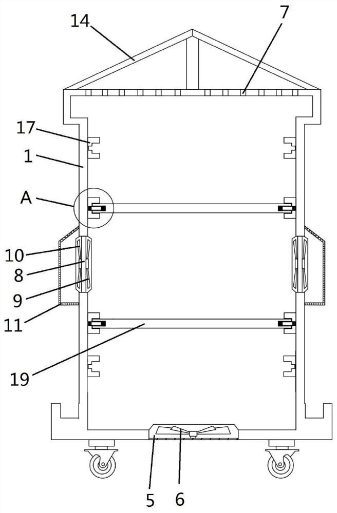
[0027] Embodiments of the present invention disclose a novel capacitor cabinet, such as Figure 1 to Figure 3As shown, it includes a cabinet body 1, a cabinet door 2 is installed on the front of the cabinet body 1, a control panel 3 and an observation window 4 are arranged on the cabinet door 2, and the inner walls of the opposite sides of the cabinet body 1 are installed sequentially from top to bottom There are a plurality of slide rails 17, and a bearing plate 19 is slidably connected between the matching slide rails 17 on both sides, and the connection between the bearing plate 19 and the slide rails 17 is provided with an elastic locking limit for fixing the two. Mechanism, the bearing plate 19 is uniformly provided with cooling holes, the bottom of the cabinet body 1 is provided with an air inlet 5, the inside of the air inlet 5 is provided with a cooling fan 6, the bottom of the air inlet 5 is installed with a dust-proof net, and the top of the cabinet body 1 is evenly o...


PUM


Abstract

The invention discloses a novel capacitor cabinet which comprises a cabinet body, a cabinet door is installed on the front face of the cabinet body, a control panel is arranged on the cabinet door, a plurality of sliding rails are sequentially installed on the inner side walls of the two opposite sides in the cabinet body from top to bottom, and a bearing plate in sliding connection with the sliding rails is arranged between the matched sliding rails on the two sides. Elastic clamping limiting mechanisms for fixedly connecting the bearing plate and the sliding rails are arranged at the joints of the bearing plate and the sliding rails, heat dissipation holes are uniformly formed in the bearing plate, an air inlet is formed in the bottom of the cabinet body, a heat dissipation fan is arranged in the air inlet, a dustproof net is mounted at the bottom of the air inlet, a plurality of air outlets are uniformly formed in the top of the cabinet body, and a rain shelter is mounted at the top of the cabinet body. A protective cover is arranged on the front face of the cabinet body, the top of the protective cover is fixedly arranged on the top of the front face of the cabinet body, electric telescopic rods are fixedly arranged at the two ends of the bottom of the front face of the cabinet body, and the tops of the electric telescopic rods are connected with the bottom of the protective cover.

Description

technical field [0001] The invention relates to the technical field of capacitor storage cabinets, in particular to a novel capacitor cabinet. Background technique [0002] Capacitor cabinets are also called capacitor compensation cabinets. Most of the load types in the power system are inductive loads. In addition, power companies widely use power electronic equipment, which makes the power factor of the grid low, and the low power factor reduces the utilization of equipment. rate, increased power supply investment, damaged the voltage quality, reduced the service life of the equipment, and greatly increased the line loss. Therefore, by connecting the capacitor compensation cabinet in the power system, the inductive load can be balanced, the power factor can be improved, and the utilization of the equipment can be improved. Rate. Various equipment such as capacitors and reactors are placed inside the capacitor cabinet to protect various capacitors and other equipment. [...

Claims


Application Information

Patent Timeline
Patent Type & Authority Applications(China)
IPC IPC(8): H02J3/18H02B1/56H02B1/52H02B1/36H02B1/30H02B1/28H02B1/052
CPCH02J3/18H02B1/565H02B1/52H02B1/28H02B1/36H02B1/052H02B1/306H02B1/303Y02E40/30
Inventor 徐峰
Owner 江苏晟海电气有限公司
Why Eureka
Try Eureka