

Method and system for starting an aircraft turboengine
A turboshaft engine, aircraft technology, applied in the direction of engine starting, machine/engine, engine components, etc., can solve problems such as fuel ignition failure or abort, excessive acceleration of the shaft, too fast entry into the ignition window, etc.
Active Publication Date: 2015-09-02
TURBOMECA SA
View PDF7 Cites 15 Cited by
- Summary
- Abstract
- Description
- Claims
- Application Information
AI Technical Summary
Problems solved by technology
[0010] In the process, this type of high-power starter makes it possible to correctly control the torque provided by this starter, and this leads to excessive acceleration of the shaft, which leads to too fast entry into the ignition window and thus to the fuel ignition failure or abort
Method used
View moreImage
Smart ImageViewing Examples

Examples
Embodiment approach
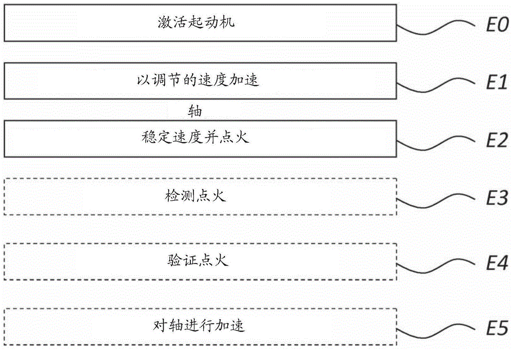
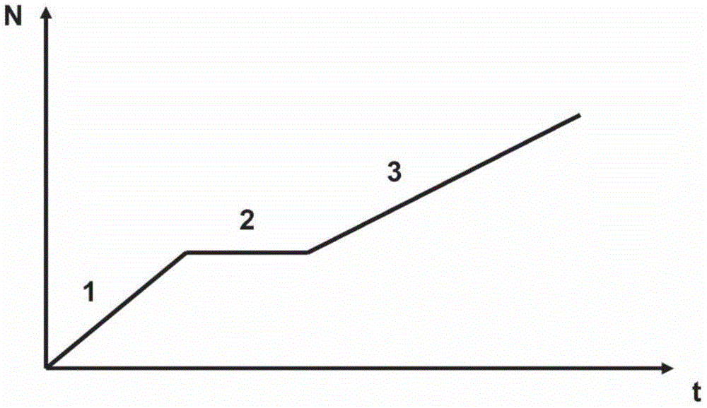
[0066] The method according to the invention is shown in figure 2 Reference image 3 Be explained.
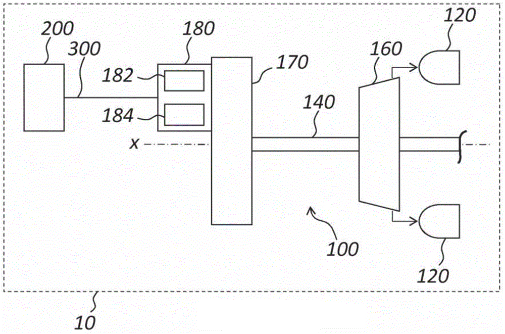
[0067] In step E0, when the turboshaft engine needs to be started on the ground or in flight, an activation command is sent to the electric starter 180, so that the electric starter provides torque to the shaft 140 via the relay transmission 170.
[0068] In step E1, the compressor shaft 140 is accelerated by the starter 180 in the first start phase P1.
[0069] In the first start phase P1, the rotation speed of the shaft 140 is adjusted so that the acceleration of the shaft 140 remains substantially constant in the first phase P1.
Login to View More PUM
 Abstract
The invention relates to a method for starting an aircraft turboshaft engine, said turboshaft engine comprising a combustion chamber, a compressor shaft on which a compressor wheel is mounted to feed compressed air to said combustion chamber, at least one starter connected to said shaft so as to provide it with a specified starting torque for driving it in rotation. The method comprises accelerating the compressor shaft during a first start-up phase, then stabilising the rotational speed of the compressor shaft during a second start-up phase. During acceleration of the compressor shaft, the rotational speed of the shaft is regulated such that the acceleration of the shaft remains substantially constant.
Description
Technical field [0001] The invention relates to a method and system for starting a turbine engine of an aircraft. Background technique [0002] In a known manner, the turbine engine of the aircraft includes a combustion chamber, a compressor shaft on which a compressor wheel is mounted to feed compressed air to the combustion chamber, and at least one compressor shaft connected to the shaft so as to provide sufficient power to drive it. A starter (or starter generator) with a rotating starting torque. [0003] In order to start the turboshaft engine, the starter first accelerates the compressor shaft in a first start-up phase, in which the fuel circuit upstream of the starter injector is pressurized and purified. Subsequently, in the second start-up phase, fuel injection is initiated before the fuel is ignited in the combustion chamber of the turboshaft engine. Finally, in the third starting phase, the starter stops running at a predetermined rotation speed, and the turboshaft en...
Claims
Login to View More Application Information
Patent Timeline
 Patent Type & AuthorityApplications(China)
IPC IPC(8): F02C7/275
CPCF02C7/268F05D2270/304F02C7/275F05D2270/04F05D2270/309F05D2260/85F02C7/264F01D19/00
Inventor皮埃尔·哈里耶特吉恩·菲利普·杰克斯·马林
OwnerTURBOMECA SA