Sand-water separator

A sand-water separation and water storage tank technology, applied in the feeding/discharging device of the sedimentation tank, the sedimentation tank, etc., can solve the problems of low efficiency, high cost, affecting the discharge of sewage up to the standard, etc.

Inactive Publication Date: 2015-09-09
JIANGSU HUITONG ENVIRONMENTAL PROTECTION EQUIP
View PDF2 Cites 4 Cited by
  • Summary
  • Abstract
  • Description
  • Claims
  • Application Information

AI Technical Summary

Problems solved by technology

[0002] With the rapid development of urban construction and the continuous growth of population, the discharge of sewage is increasing day by day. At the same time, the treatment of sewage is also facing greater challenges. The treatment of suspended solids in sewage and the separation of sand and water sedimentation are the first and most important steps in sewage treatment. The quality of the treatment directly affects the standard discharge of sewage. The traditional sand water generally uses a grit chamber for static sedimentation and then separates it. This treatment is not only costly but also has a long treatment cycle and low efficiency.

Method used


Image

  • Sand-water separator
  • Sand-water separator
  • Sand-water separator

Examples


Embodiment Construction

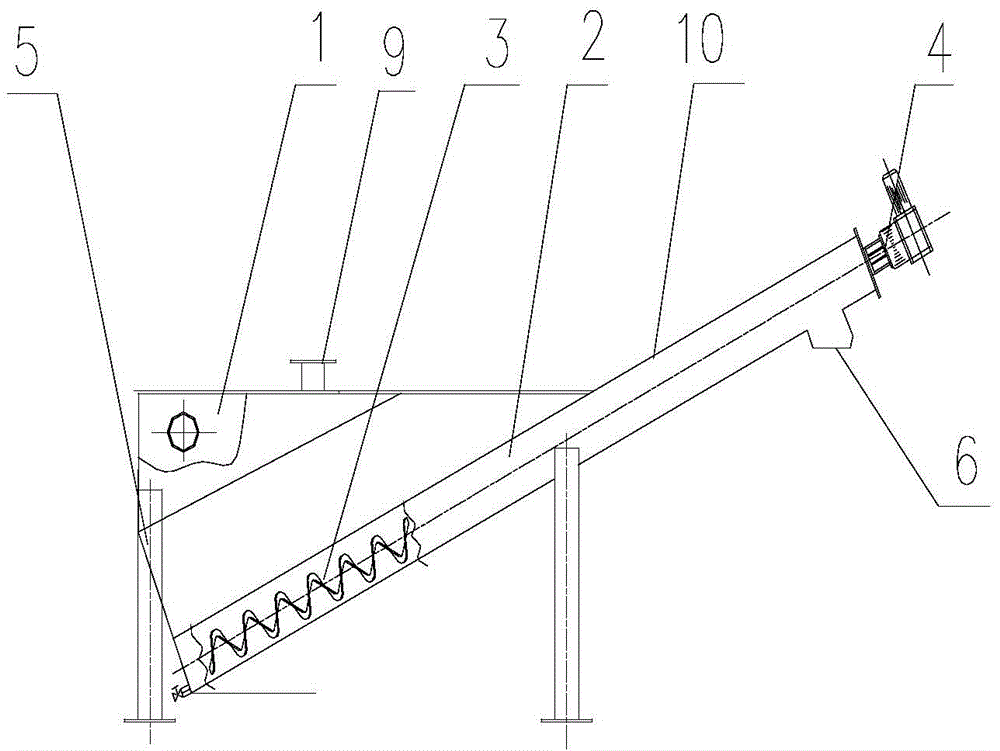
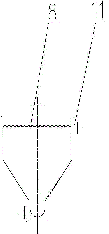
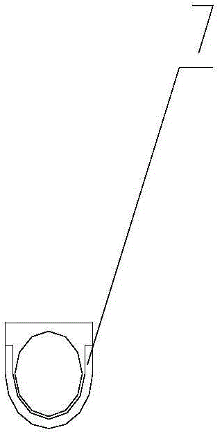
[0014] Its structure is as shown in the figure: a sand-water separator, including a water storage tank 1, a U-shaped delivery tank 2, a spiral body 3, a driving device 4 and a bracket 5, and one end of the U-shaped delivery tank is obliquely arranged on the side of the water storage tank The bottom and the other end are connected to the driving device, and the U-shaped conveying trough is provided with a sand discharge port 6 close to the driving device; the spiral body is located in the U-shaped conveying trough, and a rubber liner is also arranged between the spiral body and the U-shaped conveying trough 7. A zigzag overflow weir 8 is provided at 15-20 cm above the inner side of the water storage tank; a water inlet 9 is provided on the top of the water storage tank; a drain port 11 is provided on the upper side of the water storage tank; The spiral body adopts a stainless steel shaftless spiral body; the U-shaped conveying trough is provided with a cover 10 .


PUM


Abstract

The invention relates to a sand-water separator. The sand-water separator comprises a water storage tank, a U-shaped conveying slot, a spiral body, a driving device and a support, one end of the U-shaped conveying slot is obliquely arranged at the bottom of the water storage tank, the other end of the U-shaped conveying slot is connected with the driving device, the spiral body is positioned in the U-shaped conveying slot, and a rubber liner is arranged between the spiral body and the U-shaped conveying slot. When the sand-water separator is used, a sand-water mixed liquid is input from the top of the separator, grits settle on the dependence on gravity in the sand-water separated water storage tank, the rotation of the shaftless spiral body is used to gradually push the grits to a sand discharge opening along the U-shaped conveying slot in order to make the grits fall into a receiving cylinder and be outward transported, and separated water overflows from an overflow weir to a water discharge opening and is discharged in order to improve the operation environment and facilitate outward transportation. The sand-water separator has the advantages of compact structure, stable and safe running, easy operation and high efficiency.

Description

technical field [0001] The invention relates to the field of sewage treatment equipment, in particular to a sand-water separator. Background technique [0002] With the rapid development of urban construction and the continuous growth of population, the discharge of sewage is increasing day by day. At the same time, the treatment of sewage is also facing greater challenges. The treatment of suspended solids in sewage and the separation of sand and water sedimentation are the first and most important steps in sewage treatment. The quality of the treatment directly affects the standard discharge of sewage. The traditional sand water is generally settled in a grit chamber for settling and then separated. This treatment is not only costly, but also has a long treatment cycle and low efficiency. Contents of the invention [0003] The object of the present invention is to provide a sand-water separator with compact structure, light weight and good separation effect. [0004] In...

Claims


Application Information

Patent Timeline
Patent Type & Authority Applications(China)
IPC IPC(8): B01D21/02B01D21/24
Inventor 吴荻吴国君洪建中
Owner JIANGSU HUITONG ENVIRONMENTAL PROTECTION EQUIP
Why Eureka
Try Eureka