
Rolling device of continuous differential thick plate

A technology of differential thickness plates and rolls, which is applied in the field of continuous differential thickness plate rolling equipment, can solve the problems of not having a rolling differential thickness plate production line, affecting the surface quality of stamping parts, and complicated control technology, so as to achieve flexible production organization, Simple structure and wide adaptability

Inactive Publication Date: 2015-09-09
CHONGQING JIAOTONG UNIVERSITY
View PDF5 Cites 1 Cited by
  • Summary
  • Abstract
  • Description
  • Claims
  • Application Information

AI Technical Summary

Problems solved by technology

There are two main types of existing variable-thickness plates: one is laser tailor-welded blanks, which can reduce the weight of parts to a certain extent by using laser-tailored welded blanks, but its disadvantage is that there are welds in the transition zone, which affects the surface of stamping parts The other is the continuous differential thick plate (English name: Tailor Rolling Blanks, referred to as: TRB plate) produced by the flexible rolling production process. During the rolling process, the rollers are controlled online to adjust the gap between the upper and lower rollers. The continuous change of the thickness of the transition zone can be achieved by using distance, which solves the problems existing in laser tailor welded blanks. However, due to the complicated control technology, the variable thickness rolling mill has certain technical barriers. So far, there are only two production lines in the world, and only one in China. A production line can mass-produce rolled thick plates, and domestic large-scale steel enterprises do not have production lines for supplying rolled thick plates, and because the vertical motion of the rolls has a large inertia, it is difficult to achieve variable speed movement. The stage is adjusted at a constant speed, so it can only produce differential thick plates whose transition profile is an oblique straight line (the transition area is an inclined plane)

Method used


Image

  • Rolling device of continuous differential thick plate
  • Rolling device of continuous differential thick plate
  • Rolling device of continuous differential thick plate

Examples


Embodiment Construction

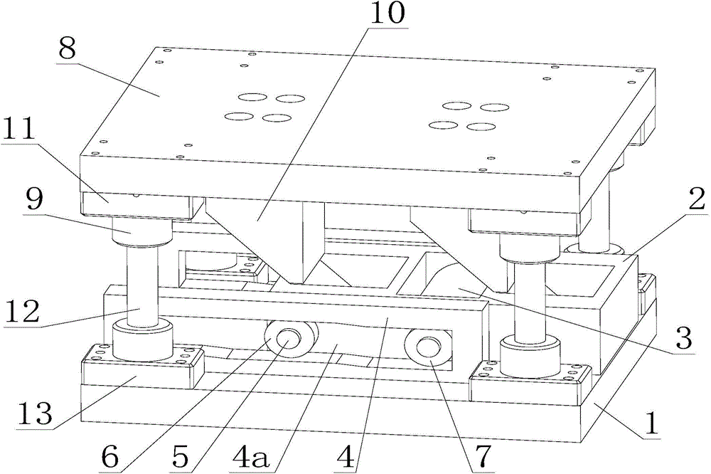
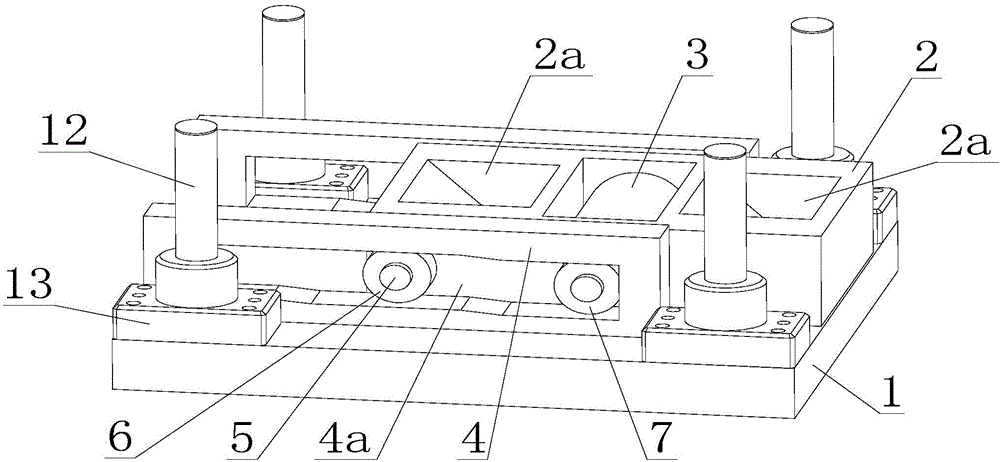
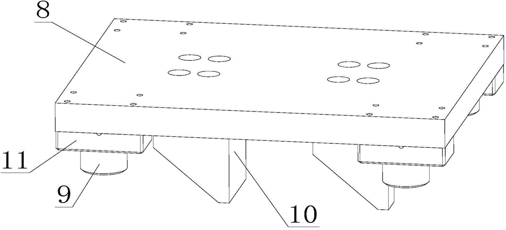
[0020] figure 1 It is a structural schematic diagram of the present invention, figure 2 It is a schematic diagram of the connecting structure of the base and the rolling mechanism of the present invention, image 3 It is a schematic diagram of the structure of the upper die as the driving mechanism of the present invention, as shown in the figure: the rolling device of the continuous differential thickness plate in this embodiment includes a base 1, a rolling mechanism slidably arranged on the base 1, for A driving mechanism that drives the rolling mechanism, wherein the base 1 is used to support and place the sheet to be processed, the rolling mechanism is used to roll the sheet, and the driving mechanism is used to drive the rolling mechanism to move laterally along the base 1 . The rolling mechanism includes a slide block 2, a roll 3 and a guide plate 4, the roll 3 is rotatably arranged in the slide block 2, the guide plate 4 is located outside the slide block 2, and the ...


PUM


Abstract

The invention discloses a rolling device of a continuous differential thick plate. The rolling device comprises a base, a rolling mechanism and a driving mechanism; the rolling mechanism is arranged on the base in a sliding mode; the driving mechanism is used for driving the rolling mechanism to move; the rolling mechanism comprises a sliding block, a roller and a guide plate; the roller is arranged in the sliding block in a rotatable mode; the guide plate is located on the outer side of the sliding block; the guide plate is detachably arranged on the base; a guide sliding groove is formed at the inner edge of the guide plate along the horizontal direction; the sliding block and the roller are connected with the guide sliding groove in a sliding mode. According to the rolling device of a continuous differential thick plate, the structure is simple, the profiling machining can be implemented, the versatility is high, the continuous differential thick plate with the transition contour which is a complex curve and the transition area which is a curved surface can be produced out according to the machining requirements, the adaptability is wide, the production organization is flexible, and the investment cost is low.

Description

technical field [0001] The invention relates to the field of variable-thickness plate processing, in particular to a rolling device for continuous differential-thickness plates. Background technique [0002] With the development of automobile lightweight, the requirements for the weight of body parts are getting higher and higher. In order to meet the lightweight requirements of body parts, variable thickness plates are usually used to reduce the weight of parts and make them meet the use requirements. There are two main types of existing variable-thickness plates: one is laser tailor-welded blanks, which can reduce the weight of parts to a certain extent by using laser-tailored welded blanks, but its disadvantage is that there are welds in the transition zone, which affects the surface of stamping parts The other is the continuous differential thick plate (English name: Tailor Rolling Blanks, referred to as: TRB plate) produced by the flexible rolling production process. D...

Claims


Application Information

Patent Timeline
Patent Type & Authority Applications(China)
IPC IPC(8): B21B1/38B21B31/02B21B37/24
CPCB21B1/38B21B31/02B21B37/24B21B2001/386
Inventor 张渝
Owner CHONGQING JIAOTONG UNIVERSITY
Learn More