Clamp used for piston rod groove milling

A piston rod and groove milling technology, which is applied in the field of piston rods, can solve the problems of easy wear and deformation of the groove, inconvenient use, and difficult disassembly, etc., and achieve the effects of firm and stable clamping, improved precision and product quality, and convenient replacement

Inactive Publication Date: 2015-09-09
ANQING TIANRUN ENG MACHINERY
View PDF7 Cites 8 Cited by
  • Summary
  • Abstract
  • Description
  • Claims
  • Application Information

AI Technical Summary

Problems solved by technology

[0003] In order to solve the above technical problems, we proposed a fixture for milling grooves of piston rods, which solves the problem of large size of the fixture, difficult disassembly, inconvenient use, poor locking, easy wear and deformation of the groove, and affects the drilling and milling accuracy and products. The problem of quality has achieved the purpose of light and durable fixture, flexible disassembly, convenient use, good stability, and improved drilling and milling precision and product quality

Method used


Image

  • Clamp used for piston rod groove milling
  • Clamp used for piston rod groove milling

Examples


Embodiment

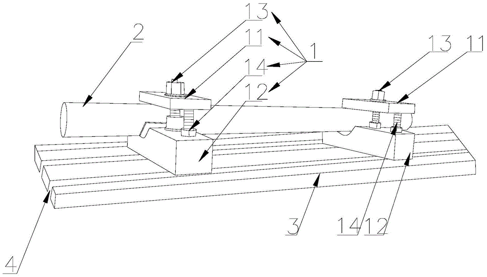
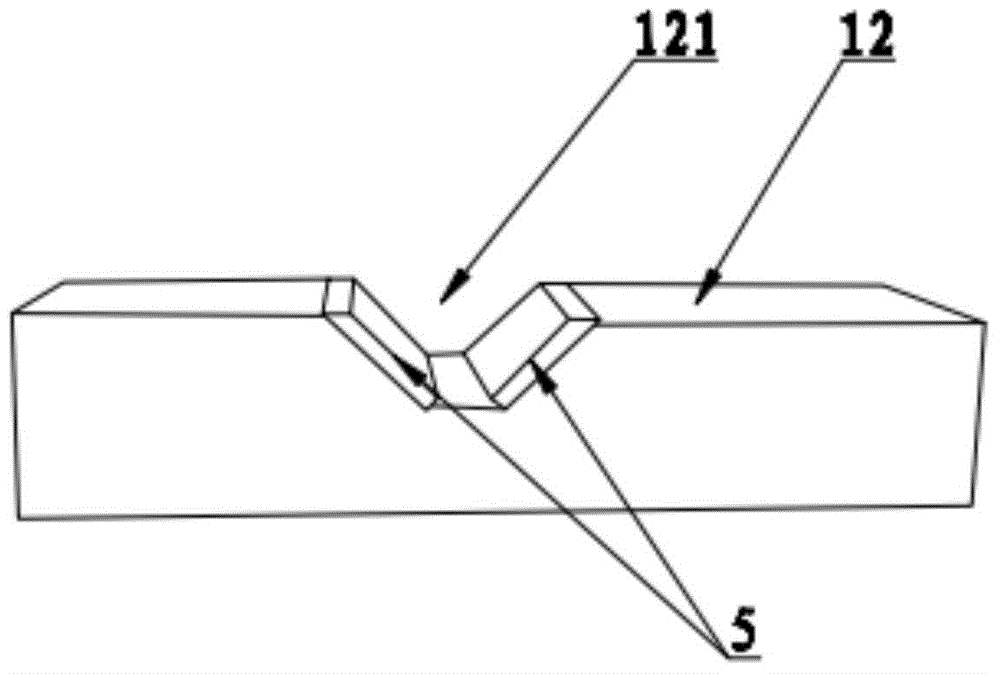
[0020] Such as Figure 1-2 As shown, a fixture for piston rod milling includes two clamping mechanisms 1 on the left and right. The clamping mechanism 1 includes an upper clamping plate 11, a lower clamping block 12, a bolt one 13 and a bolt two 14; the upper clamping plate 11 It is a rectangular structure, and the middle part of the upper splint 11 is provided with an adjustment groove (not shown) that penetrates up and down. The adjustment groove of the upper splint 11 is provided with the bolt one 13, and the lower end of the bolt one 13 Screwed to the lower clamping block 12; the lower clamping block 12 is a rectangular structure, the middle position of the top surface of the lower clamping block 12 is provided with a groove 121 in the left and right direction, the groove 121 and the upper splint 11 A piston rod 2 is arranged between them, and both ends of the piston rod 2 are fixed in the grooves 121 at both ends of the lower clamping block 12 through the upper splint 11 ...


PUM


Abstract

The invention provides a clamp used for piston rod groove milling. Regulating grooves are formed in the middles of upper clamping plates and suitable for piston rods of different sizes. Lower clamping blocks are fixed into slide grooves of a milling machine working table through second bolts, and therefore the whole clamp can be more stable. Matched spring steel plates are arranged on the two inner sides of each groove of the lower clamping blocks respectively, the grooves are protected against deformation caused by abrasion, clamping can be firmer and more stable, and the drilling and milling accuracy and the product quality are improved. Spring steel plates are locked through hexagon socket screws and are convenient to replace, and the spring steel plates are locked through the hexagon socket screws so that the flatness of the surfaces of the spring steel plates can not be influenced.

Description

technical field [0001] The invention relates to the technical field of piston rods, in particular to a clamp for milling grooves of piston rods. Background technique [0002] The piston rod for forklift needs to use drilling and milling machine in the production process, and the piston rod has a cylindrical structure, which is not easy to fix on the workbench, so it is necessary to design a fixture to realize the fixing function of the piston rod. However, the current Some fixtures are bulky and bulky; some are not easy to disassemble and are inconvenient to use; some have poor locking stability; some fixture grooves will be deformed after long-term use, affecting the stability of the clamping, and then affecting drilling and milling precision and product quality. Contents of the invention [0003] In order to solve the above technical problems, we proposed a fixture for milling grooves of piston rods, which solves the problem of large size of the fixture, difficult disas...

Claims


Application Information

Patent Timeline
Patent Type & Authority Applications(China)
IPC IPC(8): B23Q3/06
CPCB23Q3/064
Inventor 吴琪李乾龙
Owner ANQING TIANRUN ENG MACHINERY
Why Eureka
Try Eureka