Balance device and robot equipped with the balance device

A balancing device and robot technology, applied in the field of balancing devices and robots, can solve the problems of easy fatigue damage, unreasonable force, inconvenient maintenance, etc. of the cylinder, and achieve the effects of reducing material consumption, weight, and flexible and convenient operation.

Inactive Publication Date: 2017-10-20
HUBEI JITONG INTELLIGENT SCI & TECH
View PDF9 Cites 0 Cited by
  • Summary
  • Abstract
  • Description
  • Claims
  • Application Information

AI Technical Summary

Problems solved by technology

Generally, the balance cylinder is formed by a balance cylinder, which is formed of a thicker steel plate. When the balancer balances the gravity load of the boom, the gravity load all acts on the balance cylinder, and the balance cylinder Transmission force, resulting in long-term repeated work, the cylinder is prone to fatigue damage, and the entire cylinder shell needs to be replaced when fatigue damage occurs, resulting in waste
Moreover, in order to bear the gravity load of the boom, the balance cylinder is formed of a thicker steel plate as mentioned above, which leads to the weight of the existing balance device, which requires more materials, is uneconomical, and the force is unreasonable
In addition, the balance device needs to disassemble and assemble the entire balance cylinder shell during maintenance, which is time-consuming and laborious, inconvenient to maintain, and has room for improvement

Method used


Image

  • Balance device and robot equipped with the balance device
  • Balance device and robot equipped with the balance device

Examples


Embodiment Construction

[0019] Hereinafter, specific embodiments of the present invention will be described with reference to the drawings.

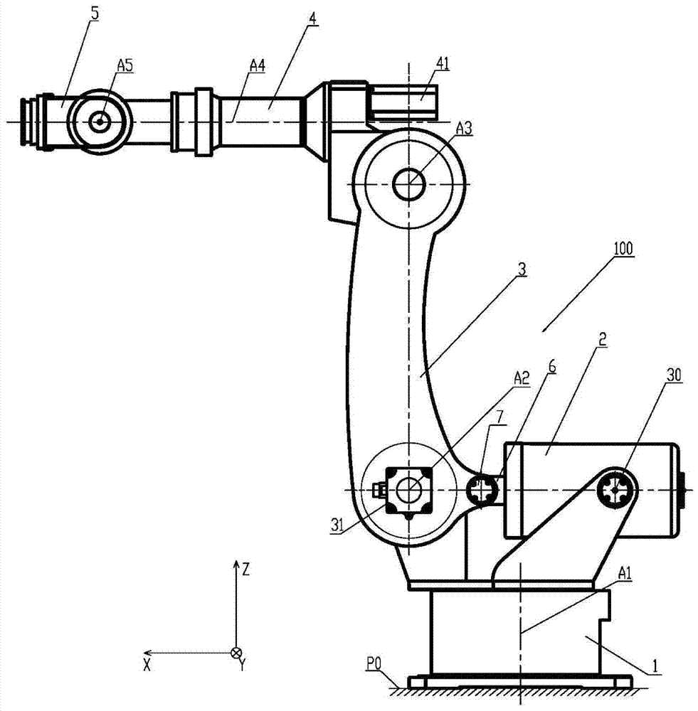
[0020] figure 1 It is an overall view showing the robot 100 provided with the balance device according to the present invention. A robot 100 according to the present invention includes a base 1 , a balance device 2 , a large arm 3 , a small arm 4 , and a wrist member 5 .

[0021] exist figure 1 In , the three-dimensional coordinate system XYZ is defined with the datum plane P0 as the reference datum. Wherein, the XY plane is parallel to the reference plane P0, and the Z axis is perpendicular to the reference plane P0. exist figure 1 Among them, the base 1 is fixed on the reference plane P0, the arm 3 is perpendicular to the reference plane P0; the forearm 4 and the wrist part 5 are perpendicular to the arm 3 and parallel to the reference plane P0. The "perpendicular" and "parallel" mentioned here do not require the angle formed by them to be 90 degrees or ...


PUM


Abstract

The invention provides a balance device and a robot comprising the same. The balance device is applied to the robot which comprises a large arm; the balance device comprises a balance cylinder, a balance cylinder shaft, a plurality of spring parts and a spring seat, wherein the plurality of spring parts are arranged in an overlapped mode and the spring seat is used for bearing one end portion of every spring part; the balance cylinder comprises a balance cylinder front cover, a balance cylinder rear cover and a cylinder body, wherein the balance cylinder front cover and the balance cylinder rear cover are arranged oppositely; the cylinder body comprises a connection part and a plurality of force transmission parts; the balance cylinder is formed by a frame, wherein the balance cylinder front cover and the balance cylinder rear cover and the connection part are connected into the frame through the plurality of force transmission parts; the connection part is located between the balance cylinder front cover and the balance cylinder rear cover; the other end portion of every spring part is borne by the balance cylinder front cover; the balance cylinder shaft leaves from or enters the balance cylinder when the large arm rotates.

Description

technical field [0001] The present invention relates to a balance device and a robot equipped with the balance device. Background technique [0002] In the past, industrial robots consisted of bases, balance devices, large arms, small arms, and wrist components. A servo motor for driving the boom to rotate is arranged in the boom. The balance device includes a balance cylinder, a plurality of overlapping spring members provided in the balance cylinder, a spring seat for supporting ends of the spring members, and a balance cylinder shaft. A joint bearing is installed on the balance cylinder shaft, and the joint bearing is connected with the boom through the balance device rotating shaft. The balance cylinder shaft is arranged to leave or enter the balance cylinder when the robot is working to compress or release a spring member provided in the balance cylinder, whereby energy can be stored in or from the spring member. components to counteract the rotational moment due to ...

Claims


Application Information

Patent Timeline
Patent Type & Authority Patents(China)
IPC IPC(8): B25J19/00B25J9/08
CPCB25J9/0048B25J19/0016
Inventor 赵双庆
Owner HUBEI JITONG INTELLIGENT SCI & TECH
Why Eureka
Try Eureka