Novel module connecting structure of locomotive

A module connection and locomotive technology, applied in the direction of locomotives, railway car bodies, railway car body parts, etc., can solve the problems of limiting the layout and size of the equipment in the car, occupying the interior space of the locomotive, and being difficult for operators to access, etc., to achieve easy maintenance. and replacement, reduce occupancy, and reduce the difficulty and cost of maintenance

Active Publication Date: 2015-09-09
CRRC ZIYANG CO LTD
View PDF7 Cites 1 Cited by
  • Summary
  • Abstract
  • Description
  • Claims
  • Application Information

AI Technical Summary

Problems solved by technology

[0004] 1) Occupies the interior space of the locomotive, which limits the layout and size of the equipment in the car
At the same time, the operation of dismantling and installation needs to be carried out inside the module. Due to space constraints, it will be difficult for operators to access, which will increase the difficulty of construction
[0005] 2) The sealing of the built-in structure is realized by the extrusion of the steel structure to the rubber strip, which requires the steel structure to have high welding and assembly precision. If the error is large, it will easily affect the sealing performance and cause rainwater to infiltrate
[0006] 3) The sealing rubber strip is hidden inside the steel structure and cannot be taken out separately. When the rubber strip is aged or damaged and leaks, it is not convenient for inspection and maintenance. When it needs to be replaced, the movable module must be lifted out as a whole. It is very inconvenient to replace the rubber strip

Method used


Image

  • Novel module connecting structure of locomotive
  • Novel module connecting structure of locomotive
  • Novel module connecting structure of locomotive

Examples


Embodiment

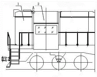
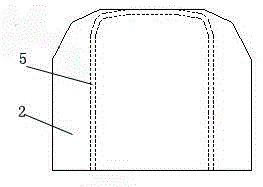
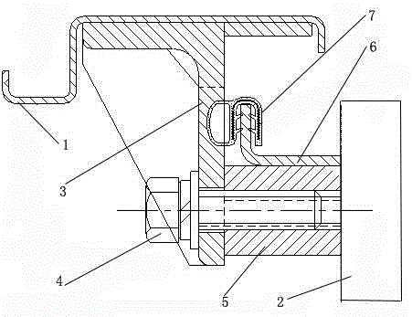
[0022] Such as Figure 4 As shown, a novel locomotive module connection structure includes a module one 1 and a module two 2, a module mounting beam 3 is arranged on the right end surface of the module one 1, a mounting seat 5 is arranged on the left end surface of the module two 2, and the module two 2 The mounting beam 3 and the mounting seat 5 are both n-shaped and have corresponding sizes and positions. The module mounting beam 3 is vertically connected to the module one 1 and its right end is bent at 90 degrees, and then it is close to the left end surface of the mounting seat 5 and fixed by several bolts 4. The two are fastened and connected. On the right end surface of the module one 1, an n-shaped connection base plate 6 is arranged on the outer surface of the module installation beam 3, corresponding to the n-shaped outer surface of the mounting seat 5, and is arranged along the outer surface of the mounting seat 5. An n-shaped rubber strip slot 8 is also provided cor...


PUM


Abstract

The invention discloses a novel module connecting structure of a locomotive. The novel module connecting structure comprises a first module and a second module; a module mounting beam is arranged on the right end surface of the first module; a mounting seat is arranged on the left end surface of the second module; the module mounting beam and the mounting seat are both n shaped and corresponding in size and position; the module mounting beam is vertically connected with the first module, and the right end of the module mounting beam is bent in 90 degrees to be closely mounted on the left end surface of the mounting seat as well as being fixedly connected through a plurality of bolts; an n-shaped connecting bottom plate is arranged on the outer side surface of the module mounting beam on the right end surface of the first module and is corresponding to the n-shaped outer side surface of the mounting seat; an n-shaped tape clamping groove is formed along the outer side surface of the mounting seat; another n-shaped tape clamping groove is correspondingly formed along the outer side surface of a connecting floor; the two tape clamping grooves are sealed and connected through a sealing tape. The novel module connecting structure has the beneficial effects that a small space in the locomotive is used; the dismounting and mounting are both performed at the outside of the locomotive; the requirements on the welding precision and assembling error are small; the sealing tape is easily overhauled and replaced.

Description

technical field [0001] The invention relates to the technical field of locomotives, in particular to a novel locomotive module connection structure. Background technique [0002] The traditional module connection structure is set inside the module, such as figure 1 , 2 , 3 shown. In the traditional built-in module connection structure, the mounting seat 5 and the mounting plate 6 are integrally formed in an "n" shape and welded to the rear wall of the driver's cab (ie figure 2 In the module 2 2) marked as 1, the sealing strip 7 is installed on the mounting plate 6 through its own clamping structure, and the module mounting beam 3 is integrally assembled and welded with other parts to form an independent electrical room module. During installation, the electrical compartment module (i.e. figure 2 The module marked as 1 in 1) is hoisted to the car body and fastened by bolt 4. During the tightening process of the bolt 4, the installation beam of the electrical room modul...

Claims


Application Information

Patent Timeline
Patent Type & Authority Applications(China)
IPC IPC(8): B61D17/00B61C17/04
CPCB61C17/04
Inventor 魏强邓茂光郭依超刘创
Owner CRRC ZIYANG CO LTD
Why Eureka
Try Eureka