Hydraulic and automatic speed-limitation compressed spring

A technology of automatic speed limit and pressure spring, which is applied in the field of mechanical parts, can solve the problems that the lowering speed cannot be adjusted, the lowering speed can be fast or slow, etc., and achieve good market prospects, fast response time, and precise control.

Inactive Publication Date: 2015-09-09
WUXI ZHONGYANG METAL PROD
View PDF7 Cites 0 Cited by
  • Summary
  • Abstract
  • Description
  • Claims
  • Application Information

AI Technical Summary

Problems solved by technology

The lowering speed of the winch wire rope used to hoist the lifeboat must meet the specification requirements. Because the load of the lifeboat equipped with the winch is heavy or light, the lowering speed of the winch wire rope can be fast or slow. The weight of the wire rope can be adjusted according to the weight of the wire rope. The existing technology is to use the extension spring design. When the shaft rotates, it drives the flying weight to rotate. The centrifugal force generated by the rotation of the flying weight makes the friction plate and the outer ring contact to generate frictional resistance. The size of the spring force under a certain load can be determined by calculation, so that the load can be lowered at a certain speed. The disadvantage of the prior art is that when the external load changes, the pulling force of the extension spring cannot be adjusted, so that the lowering speed can be reduced. There are fast and slow, which cannot be adjusted during debugging

Method used


Image

  • Hydraulic and automatic speed-limitation compressed spring
  • Hydraulic and automatic speed-limitation compressed spring

Examples


Embodiment Construction

[0011] The following will clearly and completely describe the technical solutions in the embodiments of the present invention with reference to the accompanying drawings in the embodiments of the present invention. Obviously, the described embodiments are only some, not all, embodiments of the present invention. Based on the embodiments of the present invention, all other embodiments obtained by persons of ordinary skill in the art without making creative efforts belong to the protection scope of the present invention.

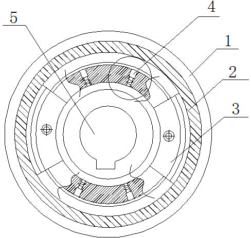
[0012] see figure 1 , the present invention provides a technical solution: a hydraulic automatic speed-limiting compression spring, including an outer ring 1, a friction plate 2, a flying block 3, a hydraulic device 4 and a shaft 5, the inner side of the outer ring 1 is a friction plate 2, so A flying block 3 is connected to the outside of the shaft 5, and the flying block 3 is in contact with the outer ring 1. A hydraulic device 4 is arranged between the flyi...


PUM


Abstract

The invention discloses a hydraulic and automatic speed-limitation compressed spring. The hydraulic and automatic speed-limitation compressed spring comprises an outer ring, a friction sheet, a fly block, a hydraulic device and a shaft, wherein the friction sheet is located at the inner side of the outer ring; the outer side of the shaft is connected with the fly block; the fly block contacts with the outer ring; the hydraulic device is arranged between the fly block and the outer ring; a hydraulic cylinder is arranged at the upper part of the hydraulic device; a washer is arranged below the hydraulic cylinder; a support post is arranged at the lower part of the hydraulic device; a pull spring winds the outer wall of the support post. The hydraulic and automatic speed-limitation compressed spring is rational in structure and practical in function; the hydraulic device is utilized for adjusting length, adjusting the size of the compression amount of the pull spring, controlling the size of the pull spring force, thereby controlling a releasing speed of a steel wire rope and enabling the speed to be adjustable. The hydraulic and automatic speed-limitation compressed spring is convenient to operate, precise to control and fast in response time, can win more time for seamen to escape or improve work efficiency, and has very good market foreground.

Description

technical field [0001] The invention relates to the field of mechanical parts, in particular to a hydraulic automatic speed-limiting pressure spring. Background technique [0002] With the rapid development of modern society and economic globalization, commodities are shipped to all parts of the world, and the most widely used mode of transportation is shipping, and maritime transportation is full of dangers. In case of shipwreck, the crew must abandon the ship and take lifeboats to escape. The speed of lifeboat release determines The crew escape time, the longer the escape time, the greater the chance of the crew being rescued. The lowering speed of the winch wire rope used to hoist the lifeboat must meet the specification requirements. Because the load of the lifeboat equipped with the winch is heavy or light, the lowering speed of the winch wire rope can be fast or slow. The weight of the wire rope can be adjusted according to the weight of the wire rope. The existing te...

Claims


Application Information

Patent Timeline
IPC IPC(8): B66D1/44
CPCB66D1/44
Inventor 孙志刚
Owner WUXI ZHONGYANG METAL PROD
Why Eureka
Try Eureka