Bridge air barrier with full automatic intelligent control

A technology of intelligent control and wind barrier, applied in construction, protective equipment, etc., can solve problems affecting driving safety, increased aerodynamic resistance of bridges, and reduced driving vision

Active Publication Date: 2015-09-09
SHANXI SHANGFENG TECH +1
View PDF9 Cites 17 Cited by
  • Summary
  • Abstract
  • Description
  • Claims
  • Application Information

AI Technical Summary

Problems solved by technology

[0004] The current wind barriers ensure the wind-shielding effect of the wind barrier by reducing the ventilation rate and increasing the height of the wind barrier. According to the working principle of the wind barrier, it can be known that the wind barrier has a higher wind-shielding efficiency when the ventilation rate is small, but Its aerodynamic resistance to the bridge will increase, which in turn affects the wind resistance safety of the bridge structure; at the same time, due to the low ventilation rate, the driving vision on the bridge deck will also be reduced accordingly, especially for cross-sea bridges, passengers cannot appreciate it when the weather is clear On the contrary, when the ventilation rate of the wind barrier is high, although the view is wide, the corresponding wind reduction effect cannot be achieved, which will affect driving safety
[0005] In order to realize the three-in-one function of bridge structure wind resistance safety, vehicle driving safety, and passenger vision effect, traditional wind barriers are difficult to meet the requirements. Therefore, research on a new type of fully automatic and intelligently controlled bridge wind barrier has become an urgent technical problem to be solved.

Method used


Image

  • Bridge air barrier with full automatic intelligent control
  • Bridge air barrier with full automatic intelligent control
  • Bridge air barrier with full automatic intelligent control

Examples


Embodiment Construction

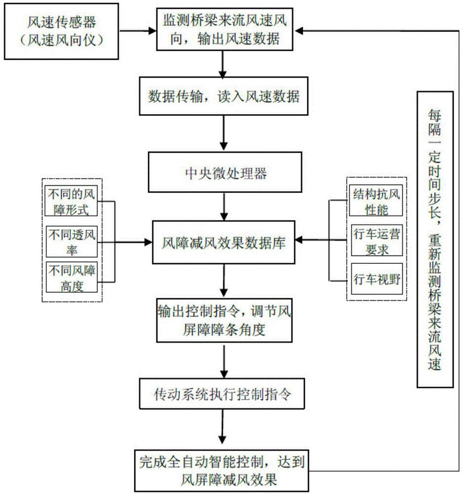
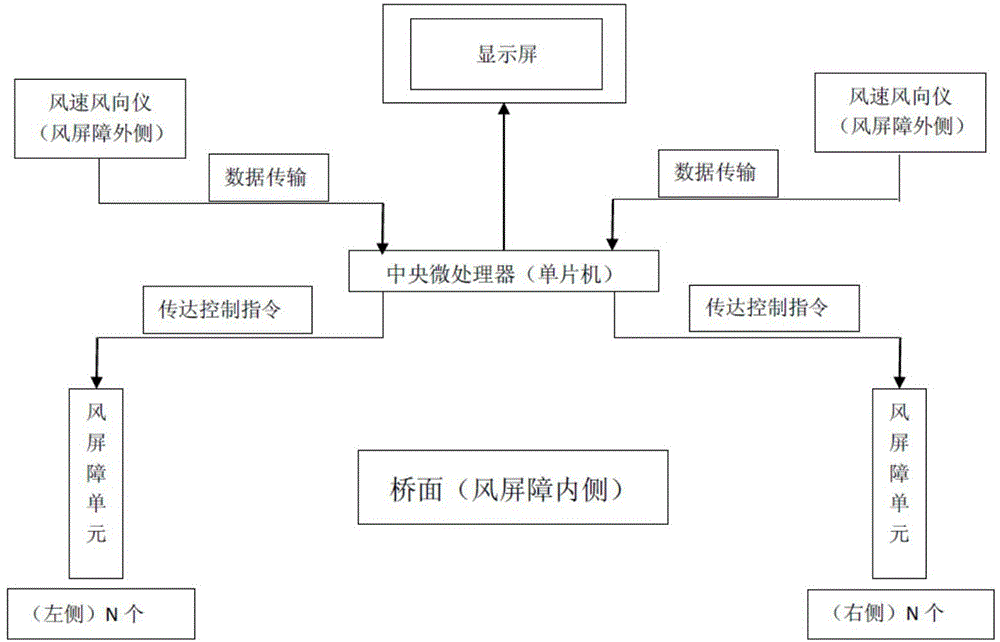
[0025] The invention includes a plurality of automatically controlled wind barrier units arranged in a line along the direction of the bridge on both sides of the bridge.

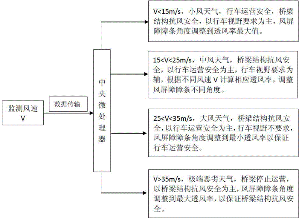
[0026] Each wind barrier unit includes a wind barrier structure system, a transmission system and a control system. The function of the wind barrier structure system is to make the structure of the wind barrier itself stable, the connection with the bridge is firm, and the effect of the barrier bars to block the wind is outstanding. The function of the wind barrier transmission system is to make the rotation of the barrier strips consistent with the transmission main shaft, and the rotation angle of the barrier strips is accurate. The function of the wind barrier control system is to make real-time and accurate monitoring of the wind speed and direction of the incoming flow on the bridge, stable data transmission, stable and efficient operation of the central microprocessor, and accurate motor rotation inst...


PUM


Abstract

The invention provides a bridge air barrier with full automatic intelligent control, comprising multiple automatically controlled air barrier units which are in linear arrangement along the bridge direction at the two sides of a bridge. Each air barrier unit comprises an air barrier structure system, an air barrier drive system and an air barrier control system. Each air barrier structure system comprises multiple air barrier strips capable of rotating along a rotary shaft. Each air barrier drive system comprises a drive gear, a drive chain, a drive main shaft and a drive motor; and the drive motor drives the air barrier strips to rotate around the rotary shaft. Each air barrier control system comprises an air speed sensor and a central microprocessor, wherein the air speed sensor is installed outside the bridge air barrier; the real-time air speed and direction data monitored by the air speed sensor are transmitted to the central microprocessor; and then the central microprocessor gives an instruction so that the air barrier strips rotate to the pointed angle; and the ventilation rate of the air barrier is automatically adjusted. The bridge air barrier with full automatic intelligent control can ensure the safety of driving under crosswind on the bridge, improve the wind-resistant performance of the bridge structure and meet the traveling vision requirement of passengers maximally.

Description

technical field [0001] The invention relates to the technical field of bridges, in particular to a fully automatic and intelligently controlled bridge wind barrier for bridges that can fully automatically and intelligently adjust the rotation angle of wind barrier bars and improve the operational safety of bridge deck vehicles. Background technique [0002] With the development of the economy, bridge spans are getting bigger and bigger, and there are more and more cross-sea and island-connecting projects. However, the characteristics of long lines of cross-sea bridges, high wind speeds on the bridge deck, and heavy traffic tasks make driving safety problems caused by wind more prominent. , the special natural wind environment where cross-sea bridges often have extremely adverse effects on the driving safety of super-long-span bridges. If the wind environment at the bridge site is bad, it will inevitably affect the driving safety of the bridge, thereby affecting the economic ...

Claims


Application Information

Patent Timeline
Patent Type & Authority Applications(China)
IPC IPC(8): E01F7/02
Inventor 李龙安孟新利庄勇苗润池刘宗福屈爱平段雪伟马润平何友娣孙英杰阮怀圣张心毅
Owner SHANXI SHANGFENG TECH
Why Eureka
Try Eureka