Micro camera well drill

A technology of cameras and drilling rigs, which is applied in construction and other fields, can solve the problems of inconvenient and inability to monitor and use in real time, and achieve the effects of convenient storage, improving drilling efficiency and reducing noise

Inactive Publication Date: 2015-09-09
连云港前沿重工机械有限公司
View PDF5 Cites 4 Cited by
  • Summary
  • Abstract
  • Description
  • Claims
  • Application Information

AI Technical Summary

Problems solved by technology

Reciprocate as follows until the drilling reaches the preset depth; the existing drilling machine is very inconvenient to use because i

Method used


Image

  • Micro camera well drill
  • Micro camera well drill

Examples


Example Embodiment

[0017] In order to make the purpose, technical scheme and advantages of this application clearer, the following combination Attached picture and specific embodiments, the present application will be described in further detail.

[0018] In the following description, references to "one embodiment," "an embodiment," "an example," "example," etc. indicate that such described embodiment or example may include a particular feature, structure, characteristic, property, element, or limitations, but not every embodiment or example necessarily includes the specific feature, structure, characteristic, property, element or limitation. Additionally, repeated use of the phrase "according to one embodiment of the present application" does not necessarily refer to the same embodiment, although it may.

[0019] For simplicity, some technical features known to those skilled in the art are omitted from the following description.

[0020] According to one embodiment of the present application,...


PUM


Abstract

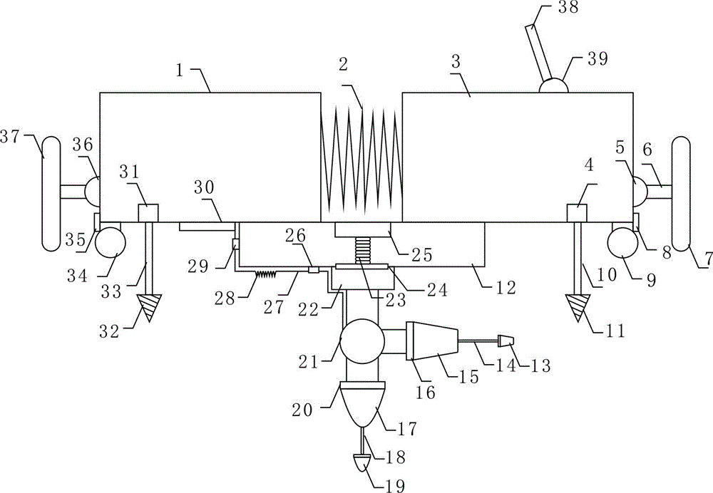
The invention provides a micro camera well drill. The micro camera well drill comprises a left base, a right base and a bottom base station which is arranged below the left base and the right base and connected with the lower end surface of the left base and the lower end surface of the right base in a sliding mode; an extensible spring is connected between the left base and the right base; the outer side end surface of the right base is provided with a right fixing table rotating shaft; the outer side end surface of the left base is provided with a left fixing table rotating shaft; the right fixing table rotating shaft is connected with a right fixing table through a rotating shaft support and the left fixing table rotating shaft is connected with a left fixing table through a rotating shaft support; the bottom of the right base is provided with a right fixing device extensible motor and a right bottom wheel.

Description

technical field [0001] The invention relates to the technical field of drilling, in particular to a drilling machine with a micro camera. Background technique [0002] Drilling is the project of using mechanical equipment to drill the formation into cylindrical holes with a certain depth. In geological and petroleum work, a cylindrical hole with a small diameter and a large depth is drilled underground by a drilling machine, also known as a borehole. The diameter and depth of the well depends on the purpose of the well and the burial depth of the minerals. Drilling machine in related art comprises top drive, drilling rod, drill bit, hoisting device, support and the standpipe for conveying drilling fluid; For lifting the top drive; the bottom of the top drive is detachably connected to the drill pipe, the lower end of the drill pipe is detachably connected to the drill bit, and one end of the riser runs through the top drive to deliver drilling fluid into the drill pipe. ...

Claims


Application Information

Patent Timeline
IPC IPC(8): E21B47/002
Inventor 陈忠辉
Owner 连云港前沿重工机械有限公司
Why Eureka
Try Eureka