Friction element carrier for clutch

A technology for friction elements and clutches, applied in the field of clutches, to achieve the effect of simplifying manufacturing

Inactive Publication Date: 2015-09-09
SCHAEFFLER TECH AG & CO KG
View PDF6 Cites 4 Cited by
  • Summary
  • Abstract
  • Description
  • Claims
  • Application Information

AI Technical Summary

Problems solved by technology

Furthermore, such blocking elements may require axial installation space, which is then no longer available for other purposes
In addition, the separate blocking element may require additional costs in the production and assembly of the clutch

Method used


Image

  • Friction element carrier for clutch
  • Friction element carrier for clutch
  • Friction element carrier for clutch

Examples


Embodiment Construction

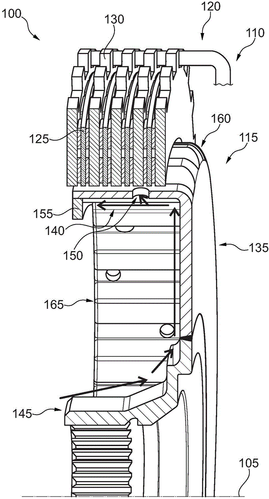
[0025] figure 1 A clutch 100 is shown for transmitting torque relative to an axis of rotation 105 . The clutch 100 is preferably designed as a wet clutch, ie it is arranged to operate in an ambient fluid 110 . Ambient fluid 110 preferably includes oil.

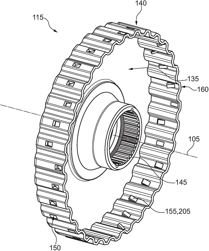
[0026] The clutch 100 includes: an inner carrier 115 , an outer carrier 120 , a first friction element 125 and a second friction element 130 . The friction elements 125 and 130 are arranged axially side by side. Preferably, a plurality of first friction elements 125 and / or a plurality of second friction elements 130 are provided, and the first friction elements and the second friction elements are arranged alternately in the axial direction. The first friction element 125 is connected by means of a toothing to the inner carrier 115 in a torque-locking manner, and the second friction element 130 is connected by means of a further toothing to the outer carrier 120 in a torque-locking manner. In the axial direction, the frict...


PUM


Abstract

A clutch is adapted to transmit torque.A carrier for a friction element of the clutch includes an axis of rotation, a radial portion and a radially outer axial portion adjacent thereto.The axial portion comprises a revolving around the rotational axis of the sheet metal part, extending alternately at different radii around the rotational axis to form an outer teeth for positive engagement in the friction element. In a region which lies on the larger radius, the sheet metal part is provided with an opening for the radial passage of a surrounding liquid and the sheet metal part bears radially inside a storage element for damming the surrounding liquid, wherein the storage element is the radial section with respect to the breakdown opposite.

Description

technical field [0001] The invention relates to a clutch for selectively transmitting torque relative to an axis of rotation. The invention relates in particular to the friction element carrier of the clutch. Background technique [0002] In a powertrain, eg for driving a motor vehicle, a clutch is provided in order to be able to interrupt the torque transmission in the powertrain. Preferably, the clutch is arranged between the transmission and the drive motor of the powertrain. In one embodiment, the clutch is a multi-plate clutch and is configured to operate in a fluid bath. The clutch's inner and outer carriers are rotatably arranged about a common axis of rotation. In the region radially between the inner carrier and the outer carrier, two friction elements are arranged axially next to each other. The first friction element is connected in a torque-locking manner to the inner carrier by means of a toothing, and the second friction element is connected in a torque-loc...

Claims


Application Information

Patent Timeline
Patent Type & Authority Applications(China)
IPC IPC(8): F16D13/58F16D13/52
CPCF16D13/683F16D13/72F16D13/74F16D2300/0214
Inventor J·芬克A·阿尔默特
Owner SCHAEFFLER TECH AG & CO KG
Why Eureka
Try Eureka