Automatic gearbox

An automatic transmission and brake technology, applied in the field of vehicle transmission, can solve the problems of difficult gear shifting, reduced transmission efficiency, low transmission efficiency, etc., and achieves the effects of easy control system design, reduced engine speed, and wide transmission ratio range

Inactive Publication Date: 2015-09-09
NANNING UNIV
View PDF6 Cites 5 Cited by
  • Summary
  • Abstract
  • Description
  • Claims
  • Application Information

AI Technical Summary

Problems solved by technology

The transmission uses 4 sets of planetary gears and 6 shifting elements. Its structure is close to that of the traditional 6AT, and it uses a dog-tooth clutch for shifting, which effectively reduces the size of the transmission. However, there are difficulties in shifting, power output shaft vibration, transmission Accidentally cut off power and other faults. Although the planetary gears are small, it does not mean that the more planetary gears, the better. Generally speaking, the more planetary gears, the more connecting elements are needed to realize the transmission of one gear. The greater the number of transmissions between planetary gears, the lower the transmission efficiency of the entire gear, and at the same time increase the requirements for hydraulic or electronic control, which increases the cost accordingly, and the failure rate of gear transmission being blocked due to damage to the connecting elements also increased
[0003] At present, the automatic transmissions used in automobiles are generally hydraulic planetary automatic transmissions (AT), dual-clutch automatic transmissions (DSG), continuously variable transmissions (CVT), etc., all of which must rely on electronically controlled hydraulic devices, which have complex hydraulic structures, Low transmission efficiency, high manufacturing and use costs, etc.

Method used


Image

  • Automatic gearbox
  • Automatic gearbox
  • Automatic gearbox

Examples


Embodiment Construction

[0038] The present invention will be further described in detail below in conjunction with the accompanying drawings, so that those skilled in the art can implement it with reference to the description.

[0039] It should be understood that terms such as "having", "comprising" and "including" as used herein do not entail the presence or addition of one or more other elements or combinations thereof.

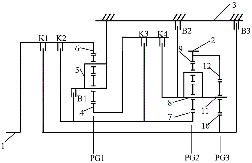
[0040] figure 1 It shows an implementation form according to the present invention, which provides an automatic transmission, including:

[0041] input axis 1;

[0042] The three planetary gear mechanisms are sequentially arranged along the axial direction of the input shaft 1 as follows:

[0043] The first planetary gear mechanism PG1, which is a single-row double-stage planetary gear mechanism, has a first sun gear 4, a first planet carrier 5 and a first ring gear 6;

[0044] The second planetary gear mechanism PG2, which is a single-row double-stage planetary gear mechanism...


PUM


Abstract

The invention discloses an automatic gearbox which comprises an input shaft, a first planetary gear mechanism, a second planetary gear mechanism, a third planetary gear mechanism, an output shaft, a first clutch, a second clutch, a third clutch, a fourth clutch and a second brake. A first gear ring is connected with the input shaft, a first planetary frame is fixedly connected with a gearbox shell, a second planetary frame is fixedly connected with a third planetary frame, the output shaft is fixedly connected with a second gear ring and a third gear ring and parallel to the input shaft, the first clutch is freely connected with the input shaft and a third sun gear, the second clutch is freely connected with the input shaft and a second sun gear, the third clutch is freely connected with a first sun gear and the second sun gear, the fourth clutch is freely connected with the first sun gear and the second planetary frame, the second planetary frame is freely fixed to the gearbox shell by the aid of the second brake, and transmission gears are determined according to the connecting state of two fastening mechanisms. The automatic gearbox is more compact in structure and wider in speed ratio range, and is provided with more gears and at most provided with twelve forward gears and one reverse gear.

Description

technical field [0001] The invention belongs to the technical field of vehicle transmission, and relates to an automatic transmission, in particular to a multi-speed line-controlled planetary gear automatic transmission. Background technique [0002] Most of the gears we know are gears with a fixed axis of rotation. In addition to rotating around its own axis, planetary gears can also revolve around the axes of other gears. Planetary gear transmission has the characteristics of small size and large carrying capacity. There are many applications in automatic transmissions of automobiles. Generally, the more gears of the transmission, the corresponding improvement in fuel economy and emission level, the smoothness of shifting, and better driving experience and fun, but the structure required for the corresponding transmission is more complicated. However, the planetary gear is Can solve this problem very well. At present, the automatic transmission gears used in automobiles ...

Claims


Application Information

Patent Timeline
Patent Type & Authority Applications(China)
IPC IPC(8): F16H3/66
CPCF16H3/66F16H2200/0078F16H2200/201F16H2200/2048F16H2200/2097
Inventor 范毅
Owner NANNING UNIV
Why Eureka
Try Eureka