Heavy-load pneumatic diaphragm actuating mechanism

A pneumatic film and actuator technology, applied in engine components, mechanical equipment, valve details, etc., can solve the problems of inability to adjust the spring installation position, single action form of the actuator, low surface accuracy, etc., to achieve convenient warehouse management and flexible use. Strong performance, flexible and convenient operation

Active Publication Date: 2015-09-09
SHANDONG FEITE AUTOMATIC CONTROL VALVE MFG CO LTD
View PDF6 Cites 1 Cited by
  • Summary
  • Abstract
  • Description
  • Claims
  • Application Information

AI Technical Summary

Problems solved by technology

However, the pneumatic membrane actuators in the prior art generally have the following disadvantages: 1. The action form of the actuator is single, and the positive and negative actuators lack versatility; 2. The diaphragm of the actuator is made of stamped steel, and the surface accuracy is not high. Heavy; 3. The position of the spring seat of the actuator is fixed, the installation position of the spring cannot be adjusted, the stroke cannot be adjusted, and it lacks flexibility

Method used


Image

  • Heavy-load pneumatic diaphragm actuating mechanism
  • Heavy-load pneumatic diaphragm actuating mechanism
  • Heavy-load pneumatic diaphragm actuating mechanism

Examples


Embodiment 1

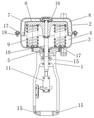
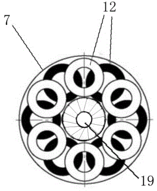
[0020] Such as figure 1 , 3 As shown, a heavy-duty pneumatic membrane actuator mainly includes a bracket 1, an upper membrane cover 2, a lower membrane cover 3, a diaphragm 6, a tray 7, a spring 9, a push rod 10 and a connecting half 11; The membrane cover 2 and the lower membrane cover 3 are fixedly connected together by bolts and nuts to form a hollow membrane chamber 4, and a guide bushing 5 is provided between the lower membrane cover 3 and the support 1, which are fixedly connected by bolts; the membrane chamber 4 A diaphragm 6, a tray 7 and a spring 9 are arranged inside, the upper diaphragm cover 2 forms a diaphragm air chamber 8 with the diaphragm 6 and the tray 7, the lower end of the spring 9 is fixed on the lower diaphragm cover 3, and its upper end abuts against the Tray 7, several springs 9 are provided between the lower membrane cover 3 and the tray 7 to form a spring chamber; corresponding holes 19 are provided in the middle of the upper membrane cover 2, the l...

Embodiment 2

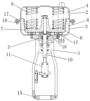
[0025] Such as figure 2 , 3 As shown, a heavy-duty pneumatic membrane actuator mainly includes a bracket 1, an upper membrane cover 2, a lower membrane cover 3, a diaphragm 6, a tray 7, a spring 9, a push rod 10 and a connecting half 11; The membrane cover 2 and the lower membrane cover 3 are fixedly connected together by bolts and nuts to form a hollow membrane chamber 4, and a guide bushing 5 is provided between the lower membrane cover 3 and the support 1, which are fixedly connected by bolts; the membrane chamber 4 A diaphragm 6, a tray 7 and a spring 9 are arranged inside, the lower diaphragm cover 3 forms a diaphragm air chamber 8 with the diaphragm 6 and the tray 7, the upper end of the spring 9 is fixed on the upper diaphragm cover 1, and its lower end abuts against Tray 7, several springs 9 are arranged between the upper membrane cover 2 and the tray 7 to form a spring chamber; corresponding holes 19 are provided in the middle of the upper membrane cover 2, the lowe...


PUM


Abstract

The invention relates to a heavy-load pneumatic diaphragm actuating mechanism. The heavy-load pneumatic diaphragm actuating mechanism mainly comprises a bracket, an upper diaphragm cover, a lower diaphragm cover, a diaphragm, a tray, springs, a push rod and a connecting half, wherein the upper diaphragm cover and the lower diaphragm cover are fixedly connected through a bolt and a nut to form a hollow diaphragm chamber; the diaphragm, the tray and the spring are arranged in the diaphragm chamber; the upper diaphragm cover, the diaphragm and the tray form a diaphragm gas chamber; the lower ends of the springs are fixed on the lower diaphragm cover, and the upper ends are butted to the tray; the multiple springs are arranged between the lower diaphragm cover and the tray to form a spring chamber; and a circular groove is formed in the tray, and is designed in a depth staggering manner. The heavy-load pneumatic diaphragm actuating mechanism is reasonable in structural design; all parts with positive and negative effects are universal; the warehouse management is facilitated; and the working efficiency is improved. The modular operation is realized through the depth staggering design of the groove of the tray; the spring action range can be adjusted according to the number of the installed springs; and the stability is high in the industrial production process.

Description

technical field [0001] The patent of the invention relates to a heavy-duty pneumatic film actuator, which belongs to the technical field of automatic adjustment control valves in industrial production processes. Background technique [0002] Pneumatic film actuator is a kind of control device in the combination instrument of pneumatic unit. In the production process, it is one of the important links of the automatic adjustment system. It receives the output signal from the control room to open and close the valve to achieve medium pressure, Automatic adjustment of temperature, flow, liquid level and other parameters, widely used in automatic adjustment and remote control of petroleum, chemical, metallurgy, electric power, pharmaceutical industries. As a common driving device for regulating valves, the dynamic diaphragm actuator is used to control and adjust the opening of the valve. The pneumatic diaphragm actuator has simple structure, reliable action, convenient maintenanc...

Claims


Application Information

Patent Timeline
Patent Type & Authority Applications(China)
IPC IPC(8): F16K31/126
CPCF16K31/1262
Inventor 靳明伟葛雪铭
Owner SHANDONG FEITE AUTOMATIC CONTROL VALVE MFG CO LTD
Why Eureka
Try Eureka