

Common-rail pipe pressure-limiting valve matching element pressure-holding stroke detecting device and measuring method
A technology of maintaining pressure stroke and detection device, which is applied in the direction of measuring device, mechanical measuring device, and testing of mechanical parts, so as to achieve the effect of simple and efficient measurement method.
- Summary
- Abstract
- Description
- Claims
- Application Information
AI Technical Summary
Problems solved by technology
Method used
Image

Examples
Embodiment Construction
[0017] The present invention will be further described below in conjunction with specific drawings and embodiments.
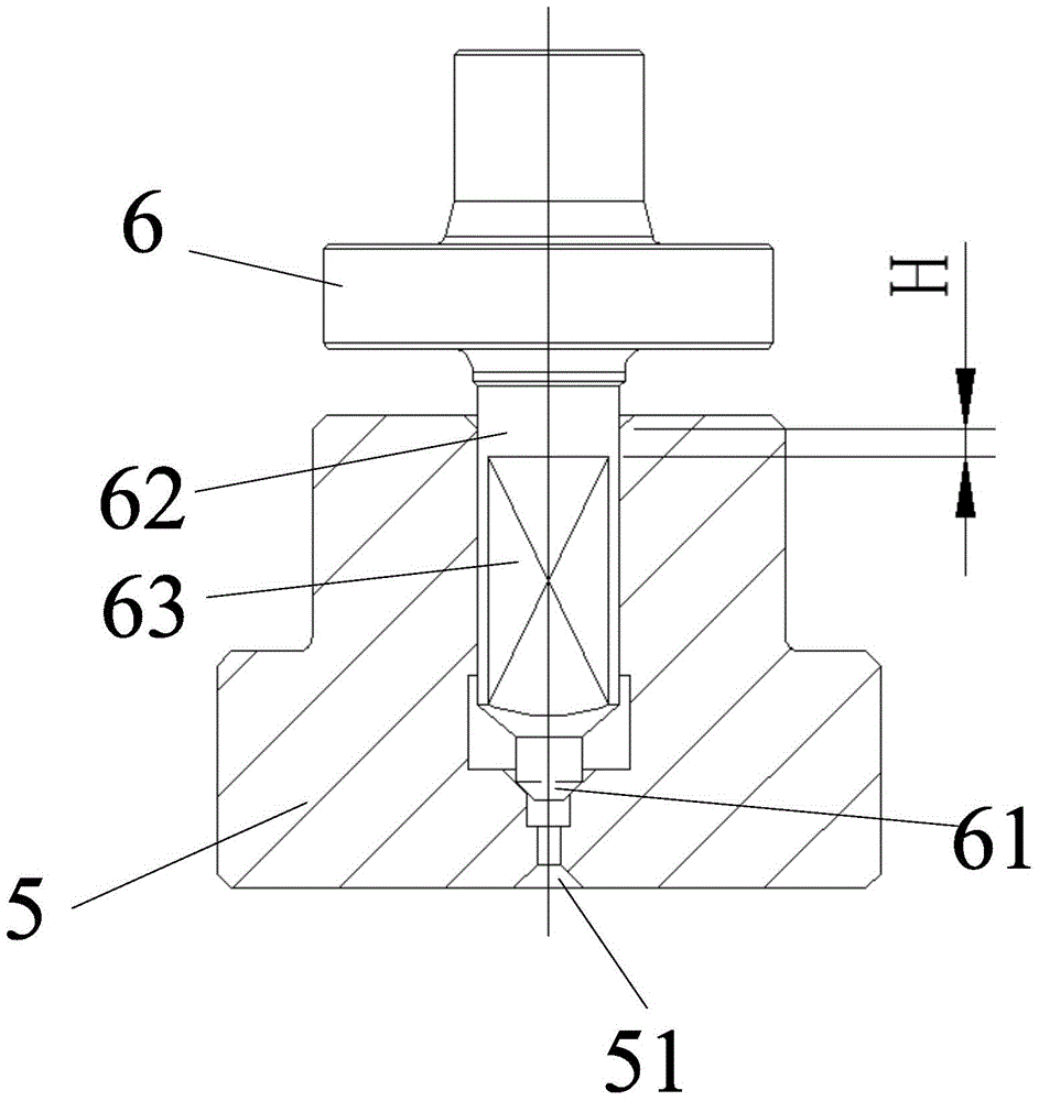
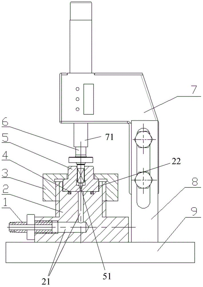
[0018] The detection device for the pressure-holding stroke of the common rail pipe pressure-limiting valve pair proposed by the present invention is as follows: figure 2 As shown, it includes a workbench 9, the valve seat positioning body 2 is fixed on the workbench 9, the valve seat positioning body 2 is provided with an air passage 21, and one end of the air passage 21 is connected to the air inlet port 1 on the valve seat positioning body, The other end is connected to the throttle hole 51 of the pressure limiting valve seat 5 fixed on the valve seat positioning body 2; the air inlet port 1 is connected to a flow meter ( figure 2 Not shown in ), real-time reaction gas flow changes.
[0019] A sealing ring 4 is provided on the valve seat positioning body 2 in contact with the pressure limiting valve seat 5, so that the pressure limiting valve seat 5 and t...
PUM
 Abstract
Description
Claims
Application Information