

Circuit and method for measuring resistance of variable resistor
A resistance and variable technology, applied in the direction of measuring resistance/reactance/impedance, measuring electrical variables, measuring devices, etc., can solve the problems of low real-time requirements, low precision requirements, short capacitor charging and discharging time, etc. Contradictory effect of measurement accuracy and measurement time
- Summary
- Abstract
- Description
- Claims
- Application Information
AI Technical Summary
Problems solved by technology
Method used
Image

Examples
Embodiment Construction
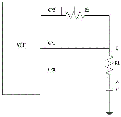
[0023] The invention provides a circuit for measuring the resistance value of a variable resistor, the schematic diagram of which is shown in image 3. The circuit includes a single-chip microcomputer, a capacitor C, a variable resistor to be measured Rx and a calibration resistor R1, one end of the capacitor C is connected to the first input and output port GP0 of the microcontroller, and the other end of the capacitor C is grounded; one end of the calibration resistor R1 A is connected to one end of the capacitor C, and the other end B of the calibration resistor R1 is connected to the second input and output port GP1 of the single-chip microcomputer; one end of the variable resistor Rx to be measured is connected to the third input and output port GP2 of the single-chip microcomputer, to be The other end of the measuring variable resistor Rx is connected to the other end B of the calibration resistor. Since the measurement accuracy of the variable resistor to be tested is ...
PUM
 Abstract
Description
Claims
Application Information