
3D localization method of Chipless RFID (Radio Frequency Identification) on the basis of printing electronic technology

An electronic, three-dimensional positioning technology, applied in the field of wireless communication and indoor positioning, can solve problems such as barcodes and two-dimensional codes.

Inactive Publication Date: 2015-09-09
杨军 +1
View PDF5 Cites 6 Cited by
  • Summary
  • Abstract
  • Description
  • Claims
  • Application Information

AI Technical Summary

Problems solved by technology

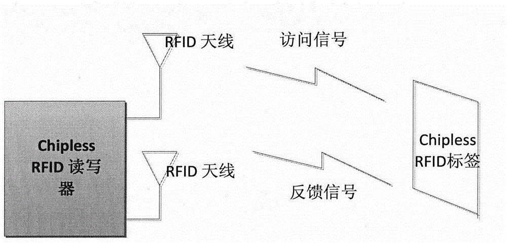
However, nothing can be perfect all at once, and there are many difficulties in the research of Chipless RFID, including how to reduce the cost of RFID to barcodes and QR codes, how to achieve a high amount of information storage under passive conditions, and how to realize self-positioning Functions, etc., while the existing Chipless RFID is basically realized by PCB technology, there are documents (Arnaud Vena, etl, "Design of Chipless RFID Tags Printed on Paper by Flexography", IEEE Transactions on Antennas and Propagation, Vol.61, No.12 , Dec.2013) reported that the metal thickness of 5 microns can be printed on paper, which is the thickest at present, but the technology in this paper is to use electroless deposition of metal copper instead of directly printing with a printer; at the same time, the literature (Rubayet-E-Azim Anee , and Nemai C.Karmakar, "Chipless RFID Tag Localization" IEEE Trans.Microw.Theory Techn., vol.61, no.11, pp.4008-4017, Nov.2013) reported the latest about Chipless RFID localization technology, But here only involves the two-dimensional positioning method of Chipless RFID

Method used


Image

  • 3D localization method of Chipless RFID (Radio Frequency Identification) on the basis of printing electronic technology
  • 3D localization method of Chipless RFID (Radio Frequency Identification) on the basis of printing electronic technology
  • 3D localization method of Chipless RFID (Radio Frequency Identification) on the basis of printing electronic technology

Examples


Embodiment Construction

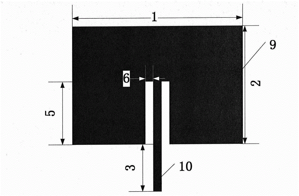
[0031]The resonant frequency of the design label here is 4.5GHz, and the dimensions: structure (1) is 42.5mm, structure (2) is 43.5mm, structure (4) is 2.2mm, structure (5) is 21mm, structure (6) is 1mm .

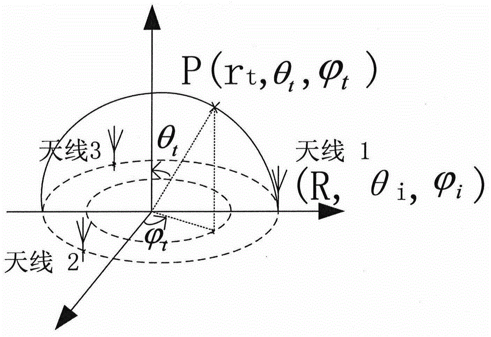
[0032] Here define φ 1 is 0 degrees, φ 2 is 120 degrees, θ 3 is 240 degrees, θ 1 , θ 2 , θ 3 is 90 degrees. According to expression (1), the distance r can be calculated from the delay time. When R is determined, r 1 , r 2 and r 3 can be obtained by expression (1), and the angular position information of the tag can be obtained by expression (3).

[0033] a) When the R radius is 1 meter,

[0034] can be tested to r 1 , r 2 and r 3 They are 1.4m, 1.4m and 1.4m respectively, and θ can be obtained by estimation t is 0 degrees, φ t is X, that is, the label is located at the top point of the sphere,

[0035] when tested to r 1 , r 2 and r 3 They are 1.6m, 1.6m and 1.6m respectively, and θ can be obtained by estimation t is 30 degrees, φ t is 120 degrees,

...


PUM


Abstract

The invention discloses a 3D localization method of Chipless RFID (Radio Frequency Identification) on the basis of a printing electronic technology, and belongs to the field of wireless communication and the Internet of Things. The technology comprises a Chipless RFID printing method, a Chipless RFID design method with a high information capacity and a 3D localization method of Chipless RFID. A Chipless RFID tag structure with the high information capacity is designed, researched nano-silver particle reagent is used as printing ink to realize a purpose that a required device is printed on paper or PET (Polyethylene Terephthalate) materials, at least three reader antennae are utilized for reading distance between the antennae and the tag structure, a corresponding mathematic model is established, and the information of a position where the tag is positioned is estimated. The 3D localization technology, which is realized by the printing electronic technology, of the Chipless RFID has the following advantages: a) tag processing is simple and convenient; b) the Chipless RFID tag is high in information capacity storage; c) the 3D localization method uses a traditional localization technology and a literature "Chipless RFID Tag Localization" method as references to propose the localization method of the Chipless RFID, and Chipless RFID localization can be realized.

Description

Technical field: [0001] The invention relates to a chipless (Chipless) RFID 3D positioning method based on printed electronic technology, which is mainly applied to the positioning technology between indoor objects and belongs to the technical field of wireless communication and indoor positioning. Background technique: [0002] Printed electronic technology has the advantages of high efficiency, fast and convenient, and can be widely used in the printing of various electronic products, such as diodes, MOS tubes, microwave devices and various circuits, so the application of printed electronic technology to RFID It has good application value and commercial prospect in design and processing. [0003] RFID (Radio Frequency Tag) has been raised to a very high position in the Internet of Everything, and is considered to be one of the foundations of the Internet of Everything. Therefore, it has been extensively studied in the academic circle and the business community in the past ...

Claims


Application Information

Patent Timeline
IPC IPC(8): G06K17/00G06K19/06
Inventor 杨军张乃柏
Owner 杨军
Learn More