Mimo antenna with improved grating lobe characteristics

A technology for antennas and transmitting antennas, applied to antenna arrays that are energized separately, independent non-interactive antenna combinations, antennas, etc., can solve problems such as high cost and complex multi-layer feedback structure

Inactive Publication Date: 2015-09-09
DELPHI TECH INC
View PDF0 Cites 34 Cited by
  • Summary
  • Abstract
  • Description
  • Claims
  • Application Information

AI Technical Summary

Problems solved by technology

However, this approach usually requires a complex multi-layer feedback structure, which leads to unnecessarily high cost

Method used


Image

  • Mimo antenna with improved grating lobe characteristics
  • Mimo antenna with improved grating lobe characteristics
  • Mimo antenna with improved grating lobe characteristics

Examples


Embodiment Construction

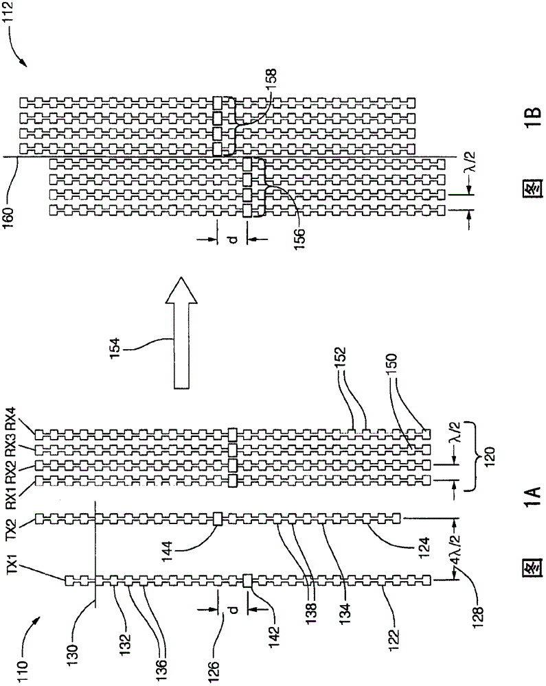
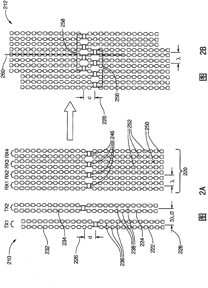
[0022] Typically, multiple-input multiple-output (MIMO) antenna architectures provide improved spatial coverage and resolution for electrical scanning. MIMO operation typically requires multiple transmit and multiple receive antennas and multiple transmitters and receivers. However, the teaching presented here is also applicable to simpler receive antenna configurations, eg a single receive antenna comprising a single element. Various configurations of MIMO antennas are described herein, where the number of transmit and receive antennas depends on the required spatial coverage and resolution in both azimuth (horizontal) and elevation (vertical) dimensions. The number of transmitters and receivers may be equal to the number of transmit and receive antennas, or a smaller number of transmitters and receivers may be time-shared between the various transmit and / or receiver antennas. However, for best performance, use parallel transmit and receive channels, one per antenna, rather ...


PUM


Abstract

A multiple input multiple output (MIMO) antenna (110, 210, 410, 510, 610, 710) for a radar system that includes a first transmit antenna (122, 222, 422, 522, 622, 722), a second transmit antenna (124, 224, 424, 524, 624, 724), and a receive antenna (120, 220, 420, 520, 620, 720). The first transmit antenna is configured to emit a first radar signal toward a target. The first transmit antenna is formed of a first vertical array (132, 232) of radiator elements (136, 236). The second transmit antenna is configured to emit a second radar signal toward the target. The second transmit antenna (110) is formed of a second vertical array (134, 234) of radiator elements (136, 236) distinct from the first vertical array (132). The receive antenna is configured to detect radar signals reflected by a target toward the receive antenna. The receive antenna is formed of a plurality of paired vertical arrays (250) of detector elements (252).

Description

technical field [0001] The present application discloses MIMO antennas with improved grating lobe characteristics. The present disclosure relates to multiple-input multiple-output (MIMO) antennas for radar systems, and more particularly to configuring transmit and receive antennas to improve grating lobe performance of the antennas. Background technique [0002] Many ground vehicle (eg automotive) radar systems in use today are only capable of determining the range and horizon or azimuth to a target or object. The transmit and receive antennas of such systems are typically vertical arrays of radiator and detector elements or patches, respectively. However, it has been recognized that it is desirable to determine the vertical or elevation angle to the object so that elevated objects such as overhanging bridges or buildings are not inadvertently determined as objects in the vehicle's path of travel. [0003] Since automotive radar systems are particularly sensitive to cost f...

Claims


Application Information

Patent Timeline
Patent Type & Authority Applications(China)
IPC IPC(8): H01Q21/00H01Q1/32G01S13/931
CPCG01S13/4463H01Q21/08H01Q13/206G01S13/42G01S7/03H01Q21/065H01Q21/28G01S13/931G01S7/2813G01S2013/0245G01S7/02G01S13/003
Inventor S·W·阿兰德
Owner DELPHI TECH INC
Why Eureka
Try Eureka