Power distribution cabinet provided with positioning protrusion

A technology for power distribution cabinets and cabinets is applied in the field of power distribution cabinets with protruding positioning, which can solve the problems of noise, hidden dangers, easy to cause impact force, etc., and achieve the effects of convenient use, reliable operation, and impact avoidance.

Inactive Publication Date: 2015-09-09
吴扬华
5 Cites 2 Cited by

AI-Extracted Technical Summary

Problems solved by technology

The closing of the door often requires the operator to perform additional operations to lock, and this kind of ...

Abstract

A power distribution cabinet with a positioning protrusion comprises a cabinet body (3) and a door plate (4), wherein the cabinet body (3) has lock jack devices (9) at an edge frame, and the door plate (4) has cylindrical lock protruding plugs (8) at the corresponding edge. Each cylindrical lock protruding plug (8) is used for being inserted in cavities (96) of the corresponding lock jack device (9). Each lock jack device (9) comprises end part walls (91), horizontal side walls (99) and a body (98) opposite to the end part walls (91), and the end part walls (91), the horizontal side walls (99) and the body (98) enclose to form the corresponding cavities (96).

Application Domain

Technology Topic

Image

  • Power distribution cabinet provided with positioning protrusion
  • Power distribution cabinet provided with positioning protrusion
  • Power distribution cabinet provided with positioning protrusion

Examples

  • Experimental program(1)

Example Embodiment

[0011] Combine below Figure 1-4 The present invention will be described in detail.
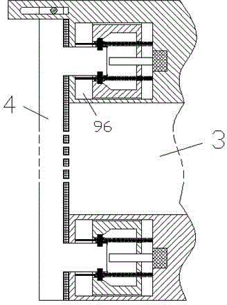
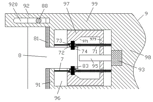
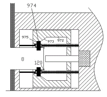
[0012] The power distribution cabinet provided with positioning projections according to the embodiment includes a cabinet body 3 with a locking jack device 9 at the frame and a door panel 4 with a cylindrical locking projection plug 8 at the corresponding edge. The protruding plug 8 is used to be inserted into the cavity 96 of the locking jack device 9. The locking jack device 9 includes an end wall 91, a lateral side wall 99, and a body 98 opposite to the end wall 91 Thereby, the cavity 96 is enclosed. The side of the door panel 4 facing the cabinet 3 is provided with an elastic sealing layer 81 for engaging with the outer side of the end wall 91, and the cavity 96 is provided with The inner side of the end wall 91 and a plurality of guide posts 7 fixedly connected to the body 98, the guide posts 7 slidably carry a locking slider assembly 72, and the locking slider assembly 72 is provided with The locking pin 74 is elastically slidable in the radial direction. The right end of the locking slider assembly 72 is provided with a positioning protrusion 120 for positioning the locking protrusion plug 8 so that the locking pin 74 can be accurately inserted into the In the locking notch 83 on the locking protruding plug 8, a spring 71 is further provided on the guide column 7 between the body 98 and the locking slider assembly 72 to hold the locking slider assembly 72 is biased to abut the limiting protrusion 73 provided on the guide post 7, and a driving sleeve 97 is also provided in the cavity 96, and the driving sleeve 97 has an inner cavity so as to face the end The outer side of the part wall 91 is open and faces the inner side of the body 98 to form an inner side wall 979. The guide column 7 and the spring 71 thereon pass through the inner cavity of the driving sleeve 97 and pass through the inner side wall. 979 is extended to the body 98, the inner side wall 979 is provided with a screw hole for threading cooperation with the screw 95 driven by the motor 93 to be able to move left and right in the axial direction, the inner cavity wall of the driving sleeve 97 A contour part 971 is provided on the upper part, and the contour groove part 971 includes a locking pin ejecting flat surface 972, a transitional inclined surface 973, a locking pin pressing down flat surface 974 and a radial end surface 975 in sequence. Driven by the motor 93, the drive sleeve 97 can eject the flat portion 972, the transition slope portion 973, and the locking pin inwardly pressing the flat portion 974 to the locking pin 74 through the locking pin. Press the locking pin 74 inward to insert it into the locking notch 83 on the locking male plug 8, and then use the engagement of the radial end portion 975 with the locking pin 74 to push the locking male plug 8 Pull to the right to press the elastic sealing layer 81 against the frame of the cabinet 3, and when the drive sleeve 97 moves to the left, the locking pin in the locking slider assembly 72 74 can slide to the left under the action of the spring 71, so as to gradually loosen the compression of the elastic sealing layer 81, and move the drive sleeve 97 to the left to the ejection plane of the locking pin. When the portion 972 is engaged with the locking pin 74, the locking pin 74 can be disengaged from the engagement with the locking recess 83, thereby The locking protruding plug 8 is allowed to be removed from the locking jack device 9.
[0013] Optionally, the locking slider assembly 72 includes a housing and a cavity 724 located between the inner side wall portion 723 and the outer side wall portion 722 of the housing, and both the inner side wall portion and the outer side wall portion are provided with a through hole. The hole is slidably fitted with the locking pin 74, the locking pin 74 is fixedly provided with a positioning ring piece 721, and a pressing spring 725 is provided between the positioning ring piece 721 and the inner side wall portion 723 for The locking pin 74 is pressed outward so that the positioning ring piece 721 can abut on the outer side wall portion 722.
[0014] Optionally, wherein the cabinet 3 is further provided with a connecting protrusion 92 with a hinge sliding groove 920 in the middle, and the hinge sliding groove 920 cooperates with a hinge shaft 88 fixedly arranged on the door panel 4 to allow The door panel 4 slides left and right relative to the cabinet 3 and is hinged to rotate.
[0015] Optionally, the numbers of the locking protruding plug 8 and the locking jack device 9 are two respectively, and they correspond one to one.
[0016] Through the above methods, those skilled in the art can make various changes according to the working mode within the scope of the present invention.

PUM

no PUM

Description & Claims & Application Information

We can also present the details of the Description, Claims and Application information to help users get a comprehensive understanding of the technical details of the patent, such as background art, summary of invention, brief description of drawings, description of embodiments, and other original content. On the other hand, users can also determine the specific scope of protection of the technology through the list of claims; as well as understand the changes in the life cycle of the technology with the presentation of the patent timeline. Login to view more.

Similar technology patents

Vehicle-mounted battery installation platform

InactiveCN104723304AAvoid shockRealize the adjustment of spatial postureWork benchesButt jointLinkage concept
Owner:王昕

Classification and recommendation of technical efficacy words

  • Avoid shock
  • Increase the locking force
Why Eureka
Try Eureka