Wing and application thereof

A technology of airfoil and spar, applied in wing and its application field

Active Publication Date: 2015-09-09
BRAYFOIL TECH PTY LTD
View PDF14 Cites 6 Cited by
  • Summary
  • Abstract
  • Description
  • Claims
  • Application Information

AI Technical Summary

Problems solved by technology

[0015] Other disadvantages of this invention include the positioning of the support structure, which fixes at least two points on th

Method used


Image

  • Wing and application thereof
  • Wing and application thereof
  • Wing and application thereof

Examples


Embodiment Construction

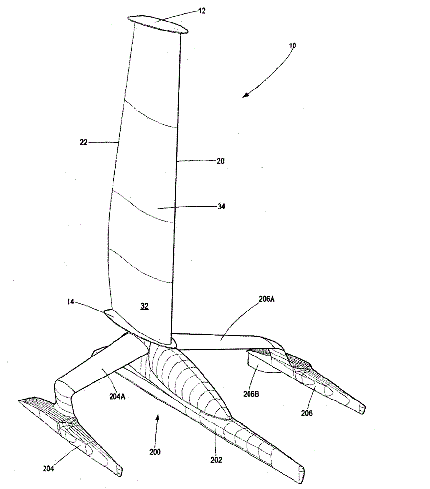
[0140] Wings according to the present disclosure including devices, systems, and methods may find application in a variety of applications. In order to provide a detailed description of the invention, the wing will be described with reference to its application as a wingsail applied to a watercraft 200 , indicated generally by the reference numeral 10 in the drawings.

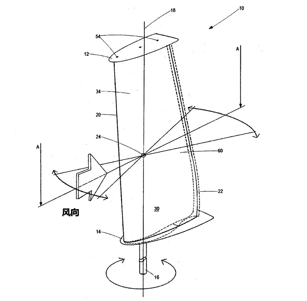
[0141] refer to figure 1 and figure 2 , the sail 10 is supported between a first end plate 12 and a second end plate 14 generally located at the operative upper and lower wing tips of the wing sail 10, respectively, the first end plate and the second end plate for An escape of the air flow from the high pressure to the low pressure side over the tip of the wing sail 10 and / or into the hollow wing sail 10 is prevented, so that the generation of eddies is prevented as much as possible. A gap (not shown) is defined between the wing sail 10 and the end plates 12 , 14 , typically closed by a gasket or seal, which...


PUM


Abstract

The present disclosure relates to a wing. More specifically, aspects of the invention relate to a variable shaped wing movable incrementally between a neutral configuration and a deformed configuration, wherein the wing takes a reflexed camber aerofoil section shape in the deformed configuration. The wing includes a first aerofoil segment and a second aerofoil segment having ends connected or fixed to one another at opposing neutral leading and trailing edges and spaced apart from one another along their lengths across a neutral mean camber line extending between the neutral leading and trailing edges to form a neutral aerofoil section of the wing. One or more actuators deform the wing between the neutral aerofoil section and a reflexed camber aerofoil section, with the first and second aerofoil segments being resilient to bias the wing towards an initial at rest aerofoil section. To cause the aerofoil section to take a reflexed camber aerofoil section, the critical buckling load of the aerofoil segments is greater than a compressive load generated in the aerofoil segments by the actuator deforming the wing between the neutral aerofoil section and the reflexed camber aerofoil section. In use, the wing is deformed by the actuator displacing two points on one of the aerofoil segments to generate the compressive load in at least such aerofoil segment. The ability of such aerofoil segment(s) to resist the compressive load causes the segment(s) to adopt a form with a point of inflection, thereby causing the wing to form the reflexed camber aerofoil section.

Description

technical field [0001] The present disclosure relates to a wing. More specifically, aspects of the invention relate to deformable wings that are incrementally movable between a neutral configuration and a deformed configuration, wherein the wing adopts a reflexed camber in the deformed configuration (camber) airfoil (aerofoil) section (section) shape. Background technique [0002] The camber of an airfoil or wing may be defined by a mean camber line, which is the curve at the center between the upper and lower surfaces of the airfoil and which passes through the leading and trailing edges of the airfoil, The leading and trailing edges are the frontmost and rearmost points, respectively. Airfoils in which this arc reverses the direction of curvature near the trailing edge are called reflex camber airfoils. [0003] A reflexed airfoil is the type of section used in flying wing aircraft due to the inherent tendency of the shape to induce a moment of torque against the traili...

Claims


Application Information

Patent Timeline
IPC IPC(8): B63H9/04B63H9/06B63H9/08
CPCB63H9/0607B63H2009/0635Y02T70/125B63B1/40B63B1/125B64C2003/142B63B2035/009B63H9/061Y02T50/10Y02T70/5236B64C3/26
Inventor 罗伯特·雷吉纳尔德·布雷
Owner BRAYFOIL TECH PTY LTD
Why Eureka
Try Eureka