Front Tiller with Depth Limiting Function

A micro-tiller, front-mounted technology, applied in the field of agricultural machinery, can solve the problems of high manufacturing difficulty, decreased work efficiency, reduced work efficiency, etc., and achieve the effects of reducing raw material and processing costs, reducing driving burden, and convenient and fast processing.

Inactive Publication Date: 2017-11-24
安徽鲁班集团神牛机械有限公司
View PDF6 Cites 0 Cited by
  • Summary
  • Abstract
  • Description
  • Claims
  • Application Information

AI Technical Summary

Problems solved by technology

[0005] 1. Since the power installation of the micro tillage machine is located or biased towards the front of the whole machine, the center of gravity of the whole machine is not at the center of the gearbox, but towards the front, so the armrest is light, and the whole machine is easy to tilt forward. In the process, the operator needs to press down on the handrail forcefully and keep it at an appropriate height with force balance, which increases the labor intensity of the operator
[0006] 2. The depth of rotary tillage cannot be accurately controlled, the tillage effect cannot ensure that the agronomic requirements are met, and the work efficiency is also greatly reduced
[0007] 3. At present, in order to prevent the operation of the micro tillage machine from pressing down too much on the handrail and losing balance and affecting safety, a resistance device is installed behind the whole machine to reduce the walking speed and limit the height of the pressing down, but the work efficiency is reduced
[0010] The above-mentioned pastoral management machines and iron wheel devices all have some shortcomings, such as: the hub structure is complex, such as processing spline grooves and inner hexagons, which is difficult to manufacture, thereby increasing the cost

Method used


Image

  • Front Tiller with Depth Limiting Function
  • Front Tiller with Depth Limiting Function
  • Front Tiller with Depth Limiting Function

Examples


Embodiment 1

[0044] In the micro tillage machine with depth limiting function according to the embodiment of the present invention, the micro tillage machine includes:

[0045] A power unit (such as a diesel engine), a rotary tiller, and a handrail, and the rotary tiller is arranged at the head of the tiller, that is, a front-mounted tiller;

[0046] A transmission device, the transmission device is arranged between the power device and the rotary tiller;

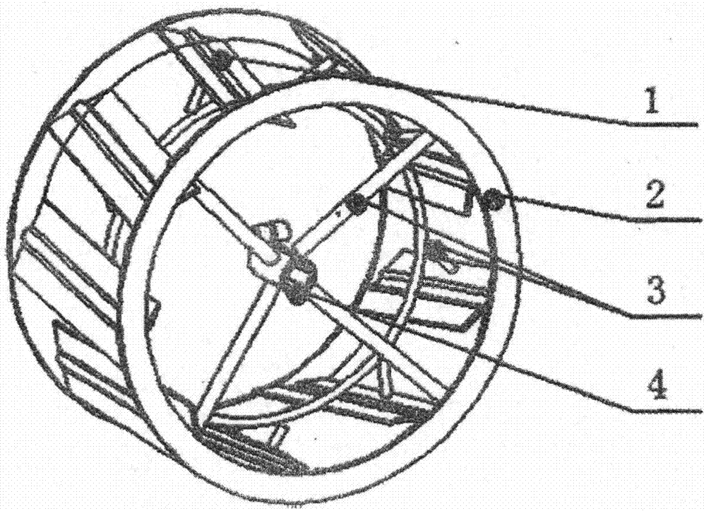
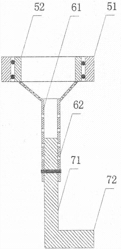
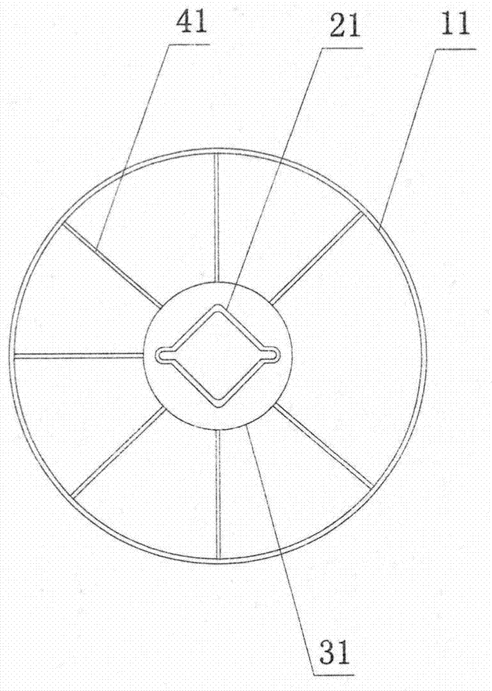
[0047] Rotating mechanism, described rotating mechanism is arranged on the bottom of described transmission device (as the fixing mount of fixed rotating mechanism); Described rotating mechanism can adopt parts such as bearing, and the outer ring 51 of bearing is fixed on the described transmission device, as figure 2 shown;

[0048] A support member, the support member is installed on the rotating mechanism; for example, the support member includes a horizontal part 72 and a vertical part 71, generally in an "L" shape, such as figu...

Embodiment 2

[0055] The micro-cultivator with depth-limiting function in this embodiment of the present invention is different from Embodiment 1 in that: the adjustment component adopts a hydraulic device, the support member is connected to the hydraulic device, and the power of the hydraulic device comes from a diesel engine.

Embodiment 3

[0057] The micro tillage machine with depth-limiting function in this embodiment of the present invention is different from Embodiment 1 in that: a blind hole is provided at the bottom of the transmission device, and one end of the tubular part is snapped into the blind hole, and one end of the tubular part is placed in the blind hole. It can rotate freely in the blind hole without breaking away from the blind hole, thereby replacing the bearing.


PUM


Abstract

The invention provides a front-set micro-tillage machine with a depth-limiting function. The micro-tillage machine comprises a machine wheel and a rotary tillage device. The micro-tillage machine further comprises a fixation frame, a rotation mechanism, a supporting part and an adjustment unit, wherein the fixation frame and the rotary tillage device are installed on the same side of the machine wheel; the rotation mechanism is directly or indirectly installed on the fixation frame; the supporting part is installed on the rotation mechanism; and the adjustment unit is used to adjust a relative distance between the supporting part and the fixation frame. The front-set micro-tillage machine with the depth-limiting function provided by the invention has the advantages such as conveniently operations, a simple structure, convenient processing, and low cost, etc.

Description

technical field [0001] The invention relates to agricultural machinery, in particular to a front-mounted tiller with a depth-limiting function. Background technique [0002] At present, among the farmland operation machinery suitable for fields such as hills and mountainous areas, as well as vegetable and orchard greenhouses, micro-tillers have been widely used due to factors such as small fields and inconvenient transfers. [0003] The basic structure of commonly used micro-tillers is as follows: the chassis uses a diesel engine or a gasoline engine, and the power is transmitted to the gearbox through a V-belt to decelerate to the output terminal for transmission. The corresponding rotating mechanism can be installed at the end to realize rotary tillage and walking operations; currently, drive and rotary tillage There are basically two types of micro tillage machines in the industry: the first is a two-wheel drive front tillage tiller, and the second is a dual-roller rotary...

Claims


Application Information

Patent Timeline
Patent Type & Authority Patents(China)
IPC IPC(8): A01B33/02A01B33/10
Inventor 刘文胜张东火尹国庆高岳陵程义明
Owner 安徽鲁班集团神牛机械有限公司
Why Eureka
Try Eureka