

Gas film face seal structure for cantilever-type foils
A gas film seal and foil technology, which is applied in the direction of engine seal, engine components, mechanical equipment, etc., can solve the problems of restricting the popularization and application of foil end face seals, high processing accuracy requirements, complex processing technology, etc., and achieve great promotion Application Potential, Increased Sensitivity, Effect of Low Machining Accuracy Requirements
- Summary
- Abstract
- Description
- Claims
- Application Information
AI Technical Summary
Problems solved by technology
Method used
Image

Examples
Embodiment Construction
[0019] The technical solution of the present invention will be described in detail below in conjunction with the accompanying drawings.
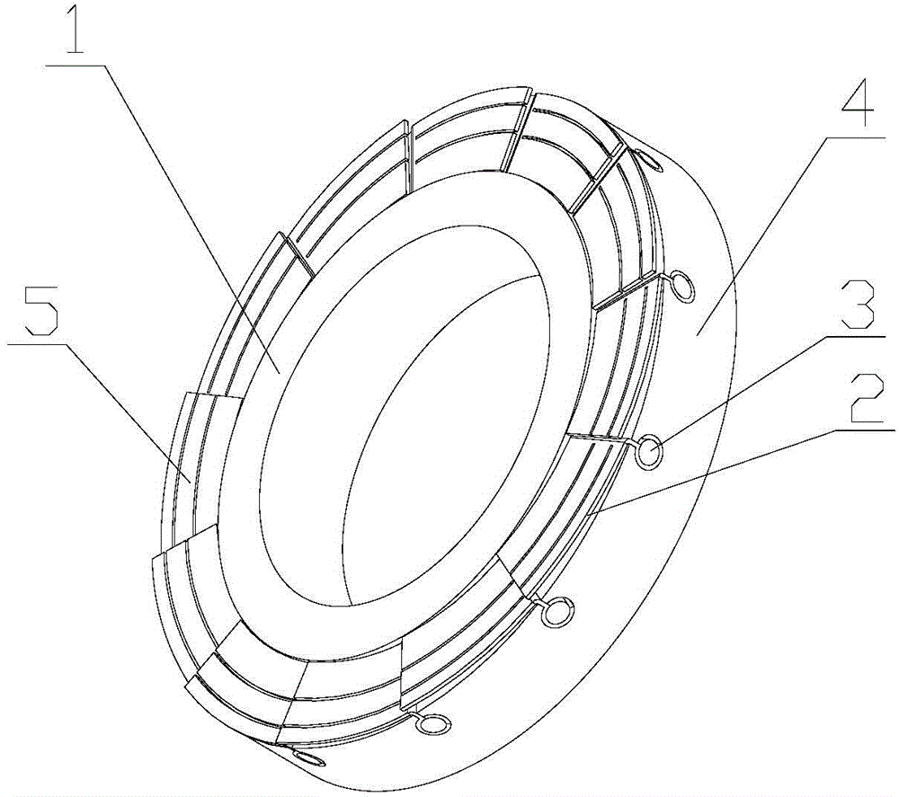
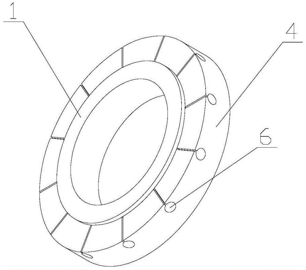
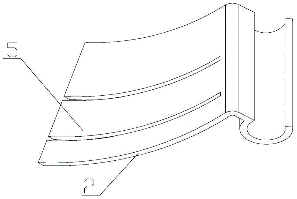
[0020] refer to Figure 1-4 As shown, a cantilever-type foil end face gas film sealing structure includes a gas-film-sealed moving ring and a static ring; the sealing end face of at least one sealing ring in the moving ring or the static ring is a cantilever-type foil end face, and the The end face of the cantilever foil includes a ring-shaped ring body 4, foil 2, and pins 3. The inner side of the ring body 4 is raised to form a ring step, and the upper surface of the ring step forms a sealing dam 1; several foils Foils 2 are laid end to end on the circular concave surface outside the sealing dam 1; the foil 2 is fan-shaped evenly distributed along the circumference, and is divided into several small pieces 5 in the radial direction from the free end to the fixed end, wherein The inner small block 5 is wider than the outer small block 5; on...
PUM
 Abstract
Description
Claims
Application Information