quick connect tube
What is Al technical title?
Al technical title is built by PatSnap Al team. It summarizes the technical point description of the patent document.
A technology for quick connection and connecting parts, which is applied in the direction of pipes, pipes/pipe joints/fittings, branch pipelines, etc., which can solve problems such as pipeline leakage, reduced sealing volume, leakage during pipe installation, etc., to achieve good sealing effect and prevent Deformation, effect of rapid intubation
Active Publication Date: 2017-05-10
RIFENG ENTERPRISE FOSHAN CO LTD +2
View PDF6 Cites 0 Cited by
Summary
Abstract
Description
Claims
Application Information
AI Technical Summary
This helps you quickly interpret patents by identifying the three key elements:
Problems solved by technology
Method used
Benefits of technology
Problems solved by technology
[0002] Quickly connect pipe fittings, the outer seal is a commonly used method, but the outer seal also has its disadvantages, the seal ring is sealed with the outer wall of the pipe, because the outer wall of the pipe is easily damaged during production, transportation, and use, resulting in pipeline leakage, so The requirements for pipe materials are very high; quick-connect pipe fittings with external sealing structure generally cannot be equipped with observation holes, and during the installation of pipes, it is easy to cause leakage due to improper installation, and the installer will draw a line to solve it, resulting in a decrease in installation speed
[0003] At present, some manufacturers modify the internal sealing structure of the O-ring. Although this structure solves the problem of observation holes and high requirements for pipe materials, there are also small leaks caused by the reduction of the sealing amount. The aging of the seal, the decrease of the sealing amount will cause the leakage of the pipeline and the failure of the product seal
Method used
Image
Click on the blue label to locate the original text in one second.
Reading with bidirectional positioning of images and text.
Examples
Embodiment Construction
[0041] In order to facilitate the understanding of the present invention, the present invention will be described more fully below with reference to the associated drawings. Preferred embodiments of the invention are shown in the accompanying drawings. However, the present invention can be embodied in many different forms and is not limited to the embodiments described herein. On the contrary, these embodiments are provided to make the understanding of the disclosure of the present invention more thorough and comprehensive.
[0042] It should be noted that when an element is referred to as being “fixed” to another element, it can be directly on the other element or there can also be an intervening element. When an element is referred to as being "connected to" another element, it can be directly connected to the other element or intervening elements may also be present.
[0043] Unless otherwise defined, all technical and scientific terms used herein have the same meaning as...
PUM
Abstract
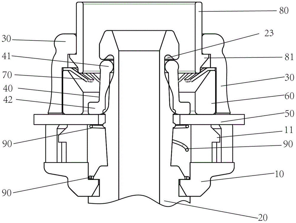
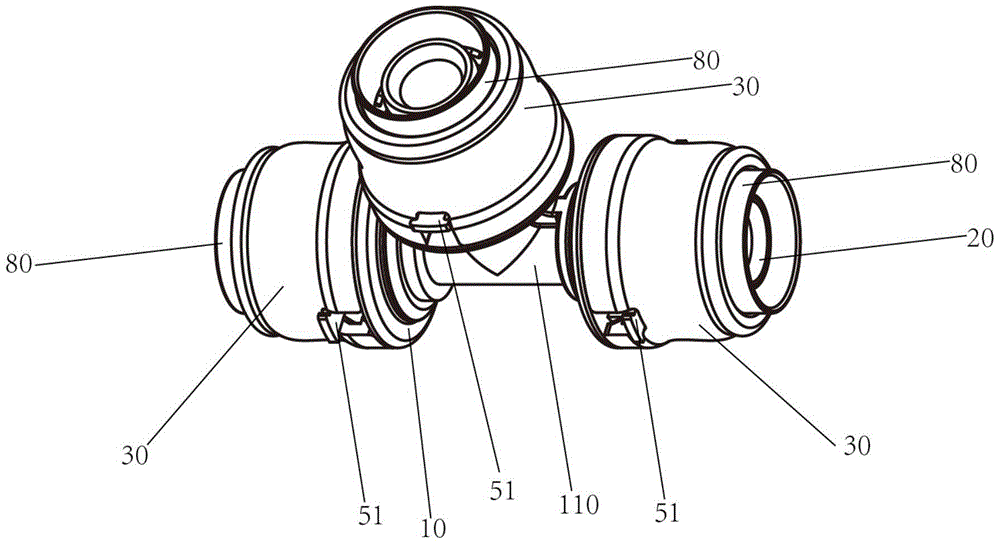
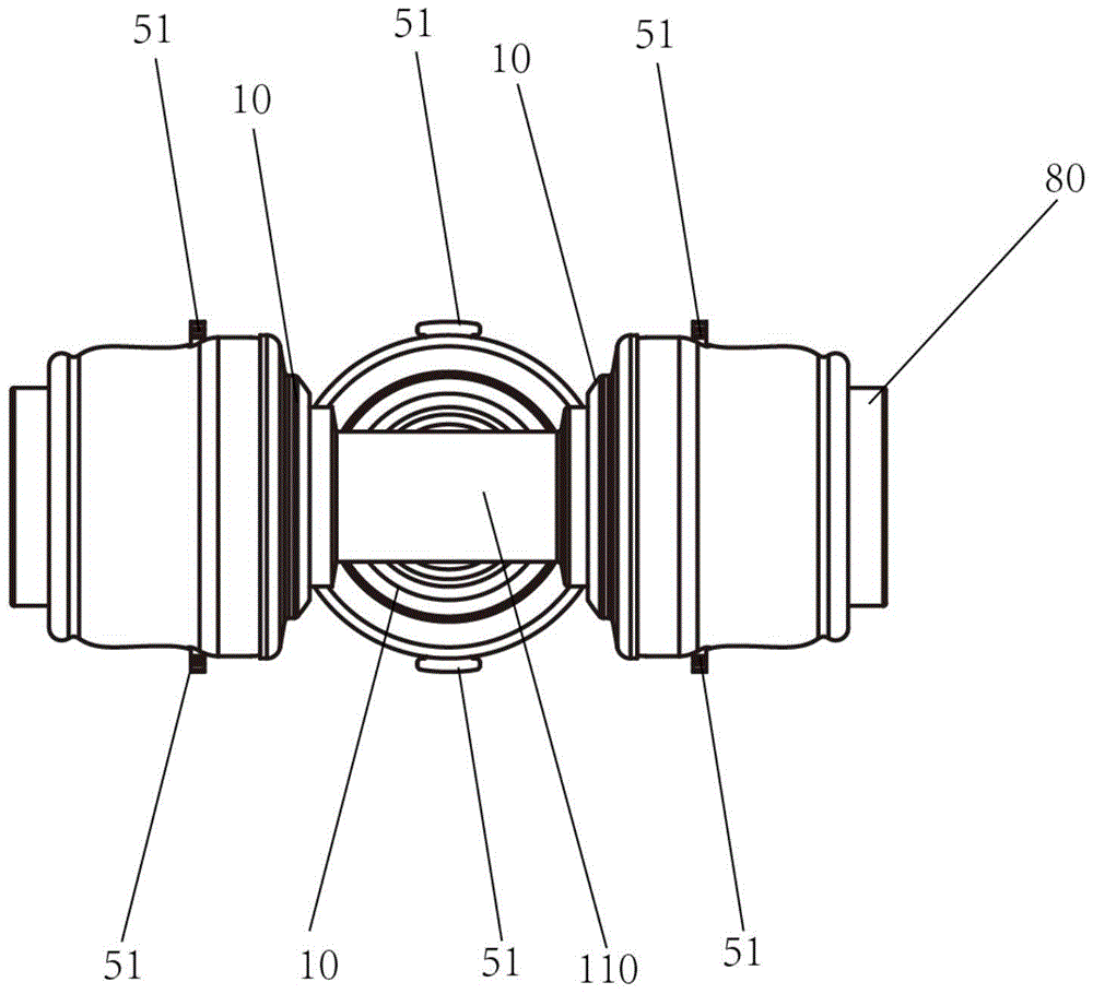
The invention discloses a quick-coupling tube which comprises a base, a main body part, cover body parts, a sealing part and a tightening ring part, the main body part is shaped like a barrel, one end of the main body part is embedded in the base, the other end of the main body part protrudes relative to the base, each cover body part is shaped like a barrel and is arranged at the end, protruding relative to the base, of the main body part in a sleeving mode, gaps are formed between the inner walls of the cover body parts and the outer wall of the main body part, the tightening ring part is shaped like a circular ring, the sealing part and the tightening ring part are arranged between the base and the main body part, the sealing part is close to the main body part, a gap is formed between the sealing part and the tightening ring part, the inner diameter of one end of the tightening ring part is smaller than that of the other end of the tightening ring part, and transmission from the end, with the big inner diameter, of the tightening ring part to the end, with the small inner diameter, of the tightening ring part is achieved in a bevel mode. According to the quick-coupling tube, the installation speed is increased, the safety and the stability are achieved, and the service life is long.
Description
technical field [0001] The invention relates to the field of pipe connection, in particular to a quick connection pipe. Background technique [0002] Quickly connect pipe fittings, the outer seal is a commonly used method, but the outer seal also has its disadvantages, the seal ring is sealed with the outer wall of the pipe, because the outer wall of the pipe is easily damaged during production, transportation, and use, resulting in pipeline leakage, so The requirements for pipes are very high; the quick-connect pipe fittings with external sealing structure generally cannot be equipped with observation holes, and the leakage caused by improper installation is easy to occur during the installation of pipes, and the installers will draw lines to solve them, resulting in a decrease in installation speed. [0003] At present, some manufacturers modify the internal sealing structure of the O-ring. Although this structure solves the problem of observation holes and high requiremen...
Claims
Application Information
Patent Timeline
Application Date:The date an application was filed.
Publication Date:The date a patent or application was officially published.
First Publication Date:The earliest publication date of a patent with the same application number.
Issue Date:Publication date of the patent grant document.
PCT Entry Date:The Entry date of PCT National Phase.
Estimated Expiry Date:The statutory expiry date of a patent right according to the Patent Law, and it is the longest term of protection that the patent right can achieve without the termination of the patent right due to other reasons(Term extension factor has been taken into account ).
Invalid Date:Actual expiry date is based on effective date or publication date of legal transaction data of invalid patent.