Lighting source and lighting device

A light source and light-emitting module technology, which is applied to lighting devices, lighting auxiliary devices, and components of lighting devices, etc., can solve the problems of lamp cap pins falling off, lamp cap pins sinking, and insufficient holding strength of lamp cap pins, so as to improve the holding strength. Effect

Active Publication Date: 2015-09-16
PANASONIC INTELLECTUAL PROPERTY MANAGEMENT CO LTD
View PDF9 Cites 2 Cited by
  • Summary
  • Abstract
  • Description
  • Claims
  • Application Information

AI Technical Summary

Problems solved by technology

[0008] In the straight-tube LED lamp described in Patent Document 1, there is a problem that the grasping strength of the cap pins of the cap is not sufficient.
[0009] For example, when a straight tube LED lamp is dropped along the long direction, the pins of the lamp head may be sunken due to the impact of the drop.
Or, the main body of the lamp cap that holds the pins of the lamp cap may break and the pins of the lamp cap may fall off

Method used


Image

  • Lighting source and lighting device
  • Lighting source and lighting device
  • Lighting source and lighting device

Examples


Embodiment approach 1

[0041] First, the straight-tube LED lamp according to Embodiment 1 of the present invention will be described. In addition, the straight tube type LED lamp which concerns on this embodiment is an example of the light source for illumination which replaces the conventional straight tube type fluorescent lamp.

[0042] [Overall structure of straight tube LED lamp]

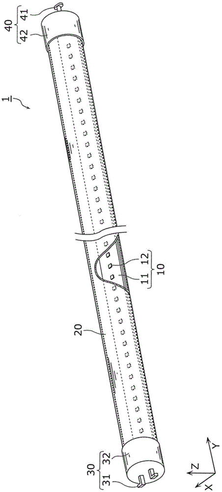
[0043] First, use figure 1 An example of the configuration of the straight tube type LED lamp according to this embodiment will be described. figure 1 It is an overview perspective view showing the straight tube type LED lamp 1 according to Embodiment 1 of the present invention.

[0044] Such as figure 1 As shown, the straight tube LED lamp 1 includes: an LED module 10, an elongated frame body 20, a lamp cap 30 for power supply and a lamp cap for non-power supply provided at each end of the frame body 20 in the longitudinal direction (direction of the tube axis). 40. The straight tube LED lamp 1 is, for example,...

Embodiment approach 2

[0156] A lighting device according to Embodiment 2 of the present invention is a lighting device including the above-mentioned light source for lighting. For example, the lighting device according to Embodiment 2 includes the straight tube LED lamp 1 according to Embodiment 1. As shown in FIG.

[0157] Figure 7 It is an overview perspective view showing an example of the lighting device 2 according to Embodiment 2 of the present invention. Such as Figure 7 As shown, the lighting device 2 according to Embodiment 2 is basic lighting, and includes a straight tube LED lamp 1 and a lighting fixture 200 .

[0158] The straight tube type LED lamp 1 is the straight tube type LED lamp 1 according to Embodiment 1, and is used as a light source for illumination of the lighting device 2 . Moreover, the illuminating device 2 which concerns on this embodiment is equipped with the two straight-pipe type LED lamps 1 as an example.

[0159] The lighting fixture 200 is electrically connec...


PUM


Abstract

The holding strength of a lamp holder pin held by a lamp holder body is improved. A linear tube LED lamp 1 comprises an elongated frame 20, an elongated LED module 10 configured in the frame 20, a power-supply lamp holder 30 which is arranged on one end of the frame 20 along the length direction and receives electric power supplied to the LED module 10, and a non-power-supply lamp holder 40 which is arranged on the other end of the frame 20 along the length direction. The non-power-supply lamp holder 40 comprises a lamp holder pin 41 and a cylindrical lamp holder body 42 arranged in an opening portion 42a and bottom 42b, and the lamp holder body 42 has a rib 43 arranged on the bottom 42b.

Description

technical field [0001] The present invention relates to a light source and a lighting device for lighting, and particularly to a light source for lighting and a lighting device including a light emitting element such as a light emitting diode (LED: Light Emitting Diode). Background technique [0002] Since LED has high efficiency and long life, it is expected to be a light source that can replace various lamps such as conventionally known fluorescent lamps and incandescent lamps. Among them, products using LED lamps (LED lamps) are being continuously researched and developed. [0003] As such an LED lamp, for example, a straight-tube LED lamp (straight-tube LED lamp) that replaces a straight-tube fluorescent lamp is known (refer to Patent Document 1). [0004] Such a straight tube LED lamp includes bases provided at both ends of an elongated outer housing, an LED module, and a lighting circuit (circuit board) for lighting the LED module. An LED module includes, for example...

Claims


Application Information

Patent Timeline
Patent Type & Authority Applications(China)
IPC IPC(8): F21S2/00F21V21/002F21Y101/02
CPCF21V19/001F21V23/06
Inventor 松本雅人北川浩规岩崎隆之
Owner PANASONIC INTELLECTUAL PROPERTY MANAGEMENT CO LTD
Why Eureka
Try Eureka