
A Polarization-Independent Beamsplitter with Adjustable Ratio of Monochromatic Light

A technology of beam splitter and monochromatic light, which is applied in the field of optics, can solve the problems that the reflective and transmissive film is well coated, the ratio cannot be well controlled, and the ratio cannot be adjusted, so as to achieve a high polarization beam splitting ratio and maintain The effect of parallelism and good coherence

Active Publication Date: 2017-11-03
UNIV OF SCI & TECH OF CHINA
View PDF4 Cites 0 Cited by
  • Summary
  • Abstract
  • Description
  • Claims
  • Application Information

AI Technical Summary

Problems solved by technology

[0002] The beam splitter is the basic device of various optical instruments and experiments. It can split a beam of light into two beams of light or combine two beams of light into one beam of light. Now the polarization-independent beam splitter of the mainstream of space light is the surface coating Type beam splitter (Beam Splitter BS for short), divided into two types: one is 45-degree type BS, but because the current coating process is difficult to coat the reflective and transmissive film well, the ratio cannot be well controlled, And often this kind of coating type BS can only achieve 50:50 for o light (ordinary light), or 50:50 for e light (extraordinary light), but cannot achieve both; the other kind of BS is 0-degree reflective BS , this kind of BS can achieve a very good splitting ratio, but because it is 0-degree reflection, it is inconvenient in practical application; and these two kinds of BSs cannot adjust the splitting ratio, and cannot achieve arbitrary ratio adjustment

Method used


Image

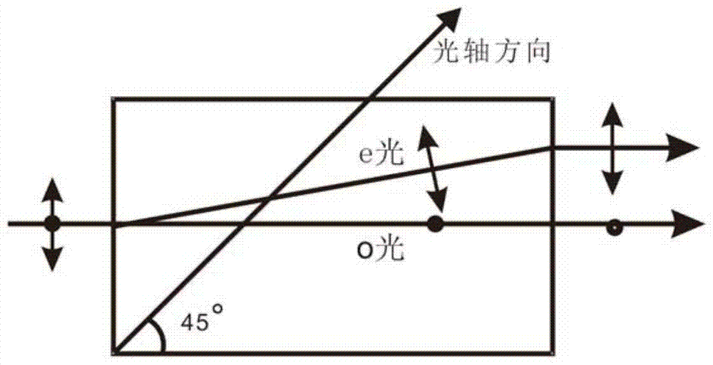
  • A Polarization-Independent Beamsplitter with Adjustable Ratio of Monochromatic Light
  • A Polarization-Independent Beamsplitter with Adjustable Ratio of Monochromatic Light
  • A Polarization-Independent Beamsplitter with Adjustable Ratio of Monochromatic Light

Examples


Embodiment

[0017] figure 1 A schematic diagram of a polarization-independent beam splitter with an adjustable ratio of monochromatic light provided by an embodiment of the present invention. Such as figure 1 As shown, it mainly includes:

[0018] The five BDs (beam displacer, beam displacer) arranged in sequence are denoted as BD1~BD5; among them, there is a half-wave plate ( figure 1 HWP1 in the) and a piece of glass compensator ( figure 1 Middle glass 1), two half-wave plates are arranged between BD2 and BD3 ( figure 1 In HWP2~HWP3), there is a half-wave plate between BD3 and BD4 ( figure 1 In HWP4), there are two half-wave plates between BD4 and BD5 ( figure 1 HWP5~HWP6) and a piece of glass compensator ( figure 1 Medium glass 2).

[0019] In the embodiment of the present invention, the BD is a natural birefringent crystal. When a beam of light is incident on the birefringent crystal, two beams of refracted light will be generated. They propagate in different directions and bec...


PUM


Abstract

The invention discloses a monochromatic light adjustable-ratio polarization-independent beam splitter comprising five light beam displacers (BDs) which are arranged in sequence and recorded as BD1-BD5. After incident light enter BD1, the incident light is divided into an upper light beam and a lower light beam; the upper light beam and the lower light beam correspondingly pass through a half wave plate and a glass compensation plate and then enter BD2, and both the upper light beam and the lower light beam are shifted downward through the spatial walk-off function of BD2; the upper light beam and the lower light beam pass through corresponding half wave plates and then enter BD3, BD3 respectively divide the upper light beam and the lower light beam into two light beams, and therefore, four light beams distributed from top to bottom are formed; the four light beams enter BD4 after passing through a half wave plate, BD4 combines the two light beams in the middle into one light beam, and therefore, three light beams distributed from top to bottom are formed; the three light beams correspondingly pass through a half wave plate, a glass compensation plate and a half wave plate and then enter BD5, BD5 combines the light beam in the middle with the upper and lower light beams respectively, and therefore, an upper light beam and a lower light beam are formed and emitted out. By adopting the beam splitter of the invention, adjustment of beam splitting in any ratio can be realized, and high precision is achieved.

Description

technical field [0001] The invention relates to the field of optical technology, in particular to a polarization-independent beam splitter with adjustable ratio of monochromatic light. Background technique [0002] The beam splitter is the basic device of various optical instruments and experiments. It can split a beam of light into two beams of light or combine two beams of light into one beam of light. Now the polarization-independent beam splitter of the mainstream of space light is the surface coating Type beam splitter (Beam Splitter BS for short), divided into two types: one is 45-degree type BS, but because the current coating process is difficult to coat the reflective and transmissive film well, the ratio cannot be well controlled, And often this kind of coating type BS can only achieve 50:50 for o light (ordinary light), or 50:50 for e light (extraordinary light), but cannot achieve both; the other kind of BS is 0-degree reflective BS , this kind of BS can achieve...

Claims


Application Information

Patent Timeline
Patent Type & Authority Patents(China)
IPC IPC(8): G02B27/28
CPCG02B27/283
Inventor 胡晓敏柳必恒黄运锋李传锋郭光灿
Owner UNIV OF SCI & TECH OF CHINA
Learn More