Structure for closing hole for hydraulic circuit

A hydraulic circuit and occlusion technology, which is applied in the direction of pressure vessels, gas/liquid distribution and storage, pipes/pipe joints/fittings, etc., can solve the problems of plug looseness, axial force disappearance, and small elastic deformation, so as to prevent leakage Effect

Inactive Publication Date: 2015-09-16
KOMATSU LTD
View PDF9 Cites 3 Cited by
  • Summary
  • Abstract
  • Description
  • Claims
  • Application Information

AI Technical Summary

Problems solved by technology

[0005] However, only a very small amount of elastic deformation of the portion where the housing groove is formed in the shaft portion can be expected.
Therefore, for example, when the head of the plug that is the contact surface is slightly plastically deformed or aged due to the influence of aging, the axial force may disappear and the plug may loosen, so that oil flows from the plug and the hydraulic circuit hole. In case of leakage from the gap between the inner peripheral surfaces of the

Method used


Image

  • Structure for closing hole for hydraulic circuit
  • Structure for closing hole for hydraulic circuit
  • Structure for closing hole for hydraulic circuit

Examples


Embodiment Construction

[0024] Hereinafter, preferred embodiments of the closing structure of the hydraulic circuit hole according to the present invention will be described in detail with reference to the drawings.

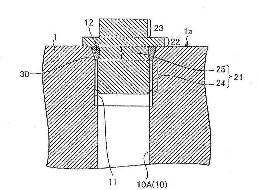
[0025] figure 1 It is a figure which shows the main part of the hydraulic equipment which applied the block structure of the hole for hydraulic circuits of embodiment of this invention. The hydraulic equipment exemplified here is an equipment in which the hydraulic circuit hole 10 is formed so as to open on the outer surface 1a of the main body 1, and the opening end of the hydraulic circuit hole 10 is closed by a plug 20, Thus, a hydraulic channel 10A is formed inside the main body 1.

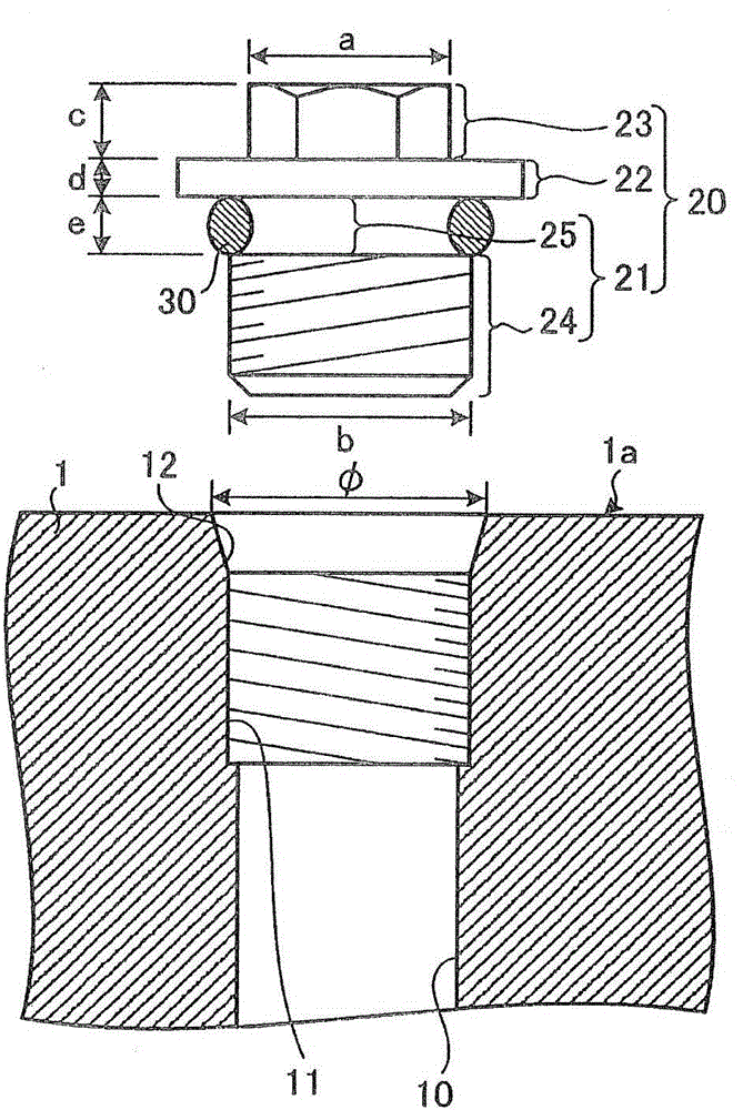
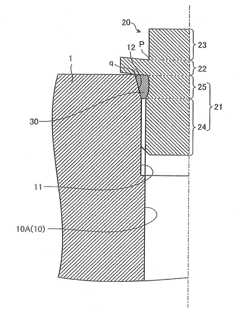
[0026] Such as figure 1 as well as figure 2 As shown, the hydraulic circuit hole 10 of the main body 1 is provided with an internal thread portion 11 and a tapered portion 12. The female screw portion 11 is configured by providing a screw groove on the inner peripheral surface of the hydraulic circuit hole...


PUM


Abstract

A structure for closing a hole for a hydraulic circuit has, in order to prevent, for a long period of time, the leakage of oil from the hole: a flange section (22) located at the base end-side portion of a receiving groove (25), in which an O-ring (30) is mounted, and having a greater outer diameter than a shaft section (21); and a polygonal column-like head section (23) which is located at the base end-side portion of the flange section (22) and to which a fastening tool is mounted. A plug (20) is configured so that: the plate thickness (d) of the flange section (22) measured in the longitudinal direction of the shaft section (21) is less than the height (c) of the head section (23); and the outer diameter (a) of the head section (23) is less than the opening diameter (φ) of the hole (10) for a hydraulic circuit. When the plug (20) is engaged through threads with the opening end of the hole (10) for a hydraulic circuit, the plug (20) is in pressure contact with the outer surface of a body with the flange section (22) serving as the seating surface.

Description

Technical field [0001] The present invention relates to a structure for closing the open end of a hole for a hydraulic circuit formed in a main body. Background technique [0002] In the case of forming a hydraulic channel and a spool valve hole inside the main body of a hydraulic equipment, a method is often used, that is, after the hole for the hydraulic circuit is formed to open on the outer surface of the main body, the plug is closed. The open end of the hole for the hydraulic circuit. The plug has a shaft portion provided with a male screw portion at the tip portion and a head portion provided at the base end portion of the shaft portion. The head is a part to which a tightening tool such as a wrench is attached, and is configured in a polygonal column shape with a larger outer diameter than the shaft. A storage groove for mounting an O-ring seal is provided at the base end of the shaft. The storage groove is a ring-shaped recess formed so that the outer diameter becomes...

Claims


Application Information

Patent Timeline
Patent Type & Authority Applications(China)
IPC IPC(8): F16J13/12
CPCF16J13/12F16L55/1108
Inventor 野原拓也筑后宽之堀秀司明石光正
Owner KOMATSU LTD
Why Eureka
Try Eureka