
Auto-counting and safeguard component of punching machine

An automatic counting and safety protection technology, applied in safety equipment, metal processing, metal processing equipment, etc., can solve problems such as failure to proceed, photoelectric protection devices interfere with normal processing, etc., to reduce labor costs, promote production automation, and improve work efficiency. Effect

Inactive Publication Date: 2015-09-23
CHENGDU DIANSHI CREATIVE TECH
View PDF6 Cites 19 Cited by
  • Summary
  • Abstract
  • Description
  • Claims
  • Application Information

AI Technical Summary

Problems solved by technology

However, for traditional punching machines, the slider drives the upper mold to reciprocate up and down for processing. During the processing, the slider must reciprocate into the processing area, resulting in the blocking of infrared rays. This action will cause serious interference to the photoelectric protection device and make normal processing impossible. conduct

Method used


Image

  • Auto-counting and safeguard component of punching machine
  • Auto-counting and safeguard component of punching machine
  • Auto-counting and safeguard component of punching machine

Examples


Embodiment 1

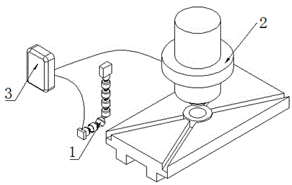
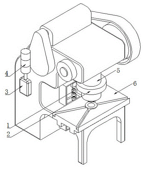
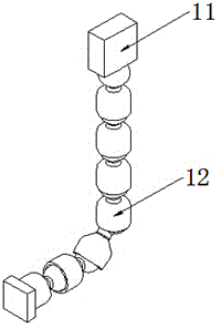
[0035] A kind of punch press automatic counting and safety protection assembly of this embodiment, such as figure 1As shown, it is mainly realized through the following technical solutions: a punch automatic counting and safety protection assembly, including an automatic counting device 1, a photoelectric protection device 2 and a control cabinet 3; the automatic counting device 1 includes a photoelectric proximity switch 11 and Flexible support 12, photoelectric proximity switch 11 is fixed on one end of flexible support 12; Described photoelectric protection device 2 comprises annular housing 21 and a plurality of photoelectric protection units 22 that are built in annular housing 21; The photoelectric protection unit 22 includes an infrared transmitter, an infrared receiver and a control circuit, and the infrared transmitter and the infrared receiver are arranged in the same direction and are all connected to the control circuit; the control cabinet 3 includes an independent...

Embodiment 2

[0038] This embodiment is further optimized on the basis of the above embodiments, such as image 3 As shown, further, the flexible bracket 12 includes a plurality of universal joints connected in series; one end of the universal joints is spherical, and the other end is conical. Other parts of this embodiment are the same as those of the foregoing embodiments, so details are not repeated here.

Embodiment 3

[0040] This embodiment is further optimized on the basis of the above embodiments, and further includes an alarm device 4 connected in series with a plurality of parallel relays. Other parts of this embodiment are the same as those of the foregoing embodiments, so details are not repeated here.


PUM


Abstract

The invention discloses an auto-counting and safeguard component of a punching machine. The auto-counting and safeguard component comprises an automatic counting device, a photoelectric protector and a control cabinet. The automatic counting device comprises a photoelectric proximity switch and a flexible support connected with each other. The photoelectric protector comprises a circular shell and a plurality of photoelectric protective units provided within the circular shell. Each photoelectric protective unit comprises an infrared transmitting end, an infrared receiving end and a control circuit; the infrared transmitting end and the infrared receiving end are co-directional and both connected with the control circuit; the control cabinet comprises an independent power supply, a counter and a plurality of relays connected in parallel; the independent power supply is connected with both the counter and the relays; the counter is electrically connected with the photoelectric proximity switch; the relays and the control circuits are connected in one-to-one correspondence. The automatic counting device is made to adapt to the processing modes of traditional punches, and a safeguard device is made to adapt to the processing modes of the traditional punches to allow safeguarding.

Description

technical field [0001] The invention relates to the technical field of automatic control of machine tools, in particular to an automatic counting and safety protection component for a punching machine. Background technique [0002] In the process of punching press processing, there are often injuries caused by the operator's fatigue production or misoperation when adjusting the workpiece to be processed, causing fingers or other parts to be squeezed in the processing area under the slider. With the increasing awareness of safety production, people use the characteristics of infrared transmission to add photoelectric protection devices on the processing operation table of the equipment to prevent human body parts from entering the processing area by mistake during processing and causing injury. The existing photoelectric protection device includes a horizontally arranged transmitter and receiver, which are arranged on both sides of the processing area: if the infrared rays em...

Claims


Application Information

Patent Timeline
IPC IPC(8): B21C51/00B21D55/00
CPCB21C51/00B21D55/00
Inventor 付裕
Owner CHENGDU DIANSHI CREATIVE TECH
Learn More