
Bending machine mold

A bending machine and mold technology, applied in the direction of forming tools, manufacturing tools, metal processing equipment, etc., can solve the problems of time-consuming, labor-intensive, cost-increasing, etc., and achieve the effect of improving overall efficiency, increasing production profits, and reducing procurement costs

Inactive Publication Date: 2015-09-23
NANJING BLESSED HYDRAULIC MACHINERY
View PDF0 Cites 5 Cited by
  • Summary
  • Abstract
  • Description
  • Claims
  • Application Information

AI Technical Summary

Problems solved by technology

[0002] Existing bending machines usually use hydraulic cylinders to drive the upper mold to press down the metal sheet placed on the lower mold to complete the bending of the metal sheet. The bending specification is mainly determined by the opening size of the lower mold during each bending. However, the opening of the lower mold in the existing bending molds is fixed, so a set of molds can only correspond to one bending specification, and there are so many bending specifications in actual production, so it has to be changed frequently Replacing molds is not only time-consuming and labor-intensive, but also the purchase of a large number of different specifications of molds also increases the cost of procurement

Method used


Image

  • Bending machine mold

Examples


Embodiment Construction

[0011] Below in conjunction with accompanying drawing and specific embodiment, further illustrate the present invention, should be understood that these embodiments are only for illustrating the present invention and are not intended to limit the scope of the present invention, after having read the present invention, those skilled in the art will understand various aspects of the present invention Modifications in equivalent forms all fall within the scope defined by the appended claims of this application.

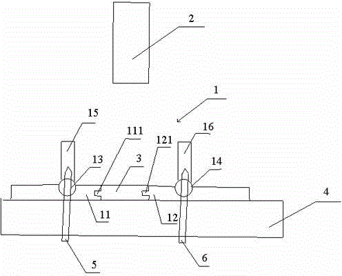
[0012] Such as figure 1 As shown, the present invention includes a lower mold 1 and an upper mold 2 placed on the hydraulic press console 4, the lower mold 1 includes a first transverse iron block 11 and a second transverse iron block 12, and the first transverse iron block 11 A groove 111 is provided on one side of the second horizontal iron block 12, a bump 121 matching the groove 111 is provided on one side of the second horizontal iron block 12, and a There is a spl...


PUM


Abstract

The invention discloses a bending machine mold, which comprises a lower mold and an upper mold placed on an operating table; the lower mold comprises a first horizontal iron block and a second horizontal iron block; one side face of the first horizontal iron block is provided with a groove; one side face of the second horizontal iron block is provided with a lug matched with the groove; a plurality of splicing iron blocks which are connected with the first horizontal iron block and the second horizontal iron block simultaneously in a clamping manner are arranged between the first horizontal iron block and the second horizontal iron block; a first idler wheel is arranged on the first horizontal iron block; a second idler wheel is arranged on the second horizontal iron block; a first longitudinal iron block is connected to the first idler wheel; and a second longitudinal iron block is connected to the second idler wheel. The opening length and the opening angle of the lower mold are adjusted, so that only one group of molds can adapt to various kinds of bending specifications, frequent replacement of the mold is not needed, the integral bending efficiency is improved, the purchasing cost is reduced, and the production profit is improved.

Description

technical field [0001] The invention specifically relates to a bending machine mold. Background technique [0002] Existing bending machines usually use hydraulic cylinders to drive the upper mold to press down the metal sheet placed on the lower mold to complete the bending of the metal sheet. The bending specification is mainly determined by the opening size of the lower mold during each bending. However, the opening of the lower mold in the existing bending molds is fixed, so a set of molds can only correspond to one bending specification, and there are so many bending specifications in actual production, so it has to be changed frequently Replacing molds is not only time-consuming and labor-intensive, but also the purchase of a large number of molds with different specifications increases the cost of procurement. Contents of the invention [0003] Purpose of the invention: In order to overcome the deficiencies in the prior art, provide a bending machine mold that ...

Claims


Application Information

Patent Timeline
Patent Type & Authority Applications(China)
IPC IPC(8): B21D37/10B21D37/02
CPCB21D37/10B21D5/06B21D37/02
Inventor 陈海楼
Owner NANJING BLESSED HYDRAULIC MACHINERY
Learn More