Machine tool set used for machining rollers in batches

A batch processing and machine tool technology, applied in the field of machine tools, can solve the problems of low working efficiency of machine tools and special maintenance of fixed tables, so as to save costs, realize mass production and improve production efficiency

Inactive Publication Date: 2015-09-23
NANJING BLESSED HYDRAULIC MACHINERY
View PDF0 Cites 0 Cited by
  • Summary
  • Abstract
  • Description
  • Claims
  • Application Information

AI Technical Summary

Problems solved by technology

[0003] Purpose of the invention: the purpose of the invention is to solve the problem that the existing machine tool has low working efficiency and the fixed table needs special maintenance

Method used


Image

  • Machine tool set used for machining rollers in batches

Examples


Embodiment 1

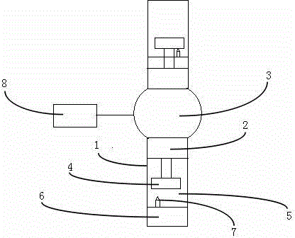
[0017] as attached figure 1 As shown, a machine tool group for batch processing rolls includes two machine tools 1, and the back contact frame 2 of the two machine tools 1 is fixedly connected to the rotating shaft 3 arranged between the two machine tools 1, and the two machine tools 1 The back contact frame 2 of the machine tool 1 is provided with a chuck 4 for fixing the workpiece. The positions where the chucks 4 of the two machine tools 1 protrude are the same, and the workbenches 5 of the two machine tools 1 are also provided with a fixing seat 6. Wherein the fixed seat 6 of one machine tool 1 is arranged on the outer side of the circle with the chucks 4 of two machine tools 1 as the diameter, and the fixed seat 6 of another machine tool 1 is arranged on the outer side of the circle with the chucks 4 of the two machine tools 1 as the diameter. On the inner side of the circle, the two fixed seats 6 are provided with a drill bit 7 facing the chuck 4 and the two machine tool...

Embodiment 2

[0020] A machine tool group for batch processing rolls, including four machine tools 1, the angle between two of the four machine tools 1 is 90°, and the back contact frames 2 of the four machine tools 1 are all connected to the four machine tools 1. The rotating shaft 3 is fixedly connected, and the contact frame 2 on the back of the four machine tools 1 is provided with a chuck 4 for fixing the workpiece. The positions where the chucks 4 of the four machine tools 1 protrude are the same. 5 are also provided with fixed seats 6, wherein the fixed seats 6 of the two machine tools 1 are arranged on the outside of the circle with the chucks 4 of the four machine tools 1 as the diameter, and the fixed seats 6 of the other two machine tools 1 are arranged on four The chuck 4 of the machine tool 1 is the inner side of the circle of the diameter, and the drill bits 7 facing the chuck 4 are all provided on the four fixed seats 6 . The rotating shaft 3 is fixedly connected with the ste...


PUM

PropertyMeasurementUnit
Angleaaaaaaaaaa

Abstract

The invention discloses a machine tool set used for machining rollers in batches. The machine tool set comprises at least two machine tools which are arranged back to back. Besides, back contact frames are fixedly connected with a rotary shaft disposed between the two machine tools. The back contact frames of the two machine tools are provided with chucks used for fixing workpieces. Extending positions of the chucks of the two machine tools are the same. Worktables of the two machine tools are both provided with a fixing base. The fixing base of one machine tool is disposed on the outer side of a circle with the chucks of the two machine tools as a diameter. The fixing base of the other machine tool is arranged on the inner side of the circle with the chucks of the two machine tools as the diameter. The two fixing bases are both provided with a drill bit towards the corresponding chuck. By the adoption of the design, the mode that a stepping motor and an annular table are combined in work is adopted, and both the front sides and the back sides of the workpieices can be worked; the conveying procedure of at least one mechanical arm is omitted; cost of at least one mechanical arm is saved; and meanwhile efficiency is improved.

Description

technical field [0001] The invention relates to a machine tool, in particular to a machine tool group for batch processing rolls. Background technique [0002] Existing machine tools generally use a one-to-one working method to process workpieces. To complete a process, it needs to be transported by mechanical claws, or transported by a conveyor belt driven by a hydraulically driven motor, so that it can reach the next process to complete processing, which is time-consuming and laborious. . At the same time, the existing machine tool can adapt to the change of the chuck of the machine tool by adjusting the position of the fixed table. However, the adjustment of the fixed table requires special personnel management, otherwise the processing yield will be affected. Contents of the invention [0003] Purpose of the invention: The purpose of the invention is to solve the problems of low working efficiency of the existing machine tools and the need for special maintenance of t...

Claims


Application Information

Patent Timeline
IPC IPC(8): B23B41/00
CPCB23B41/00
Inventor 陈海楼
Owner NANJING BLESSED HYDRAULIC MACHINERY
Why Eureka
Try Eureka