Cutting machine

A technology of cutting machine and feeding mechanism, which is applied to metal processing machinery parts, driving devices, metal processing equipment, etc., can solve the problems of narrow application area, inability to cut, and large loss of cutting parts, and achieve the effect of realizing processing requirements.

Inactive Publication Date: 2015-09-23
广州精准机械有限公司
View PDF7 Cites 3 Cited by
  • Summary
  • Abstract
  • Description
  • Claims
  • Application Information

AI Technical Summary

Problems solved by technology

[0003] 1. Mechanical cutting is generally used for materials with small cutting surface thickness or relatively soft materials. If it is used on materials with large cutting surface thickness or relatively hard metal materials, the loss of cutting parts on the cutting equipment will be greater Or it cannot be cut, and the applicable surface is relatively narrow;
[0004] 2. Existing thermal cutting equipment is generally used for cutting profiled steel with flat and straight cutting surfaces, such as channel steel, angle iron, I-beam and other profiled steel raw materials, because the cutting surface contains multiple planes in different directions. When the cutting paths on the two planes are inconsistent, the existing thermal cutting equipment cannot automatically perform continuous cutting at one time, and often needs to be divided into multiple steps, which reduces the efficiency of equipment operation

Method used


Image

  • Cutting machine
  • Cutting machine

Examples


Embodiment Construction

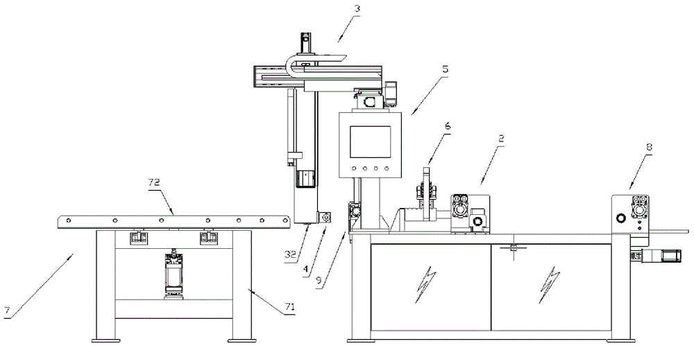
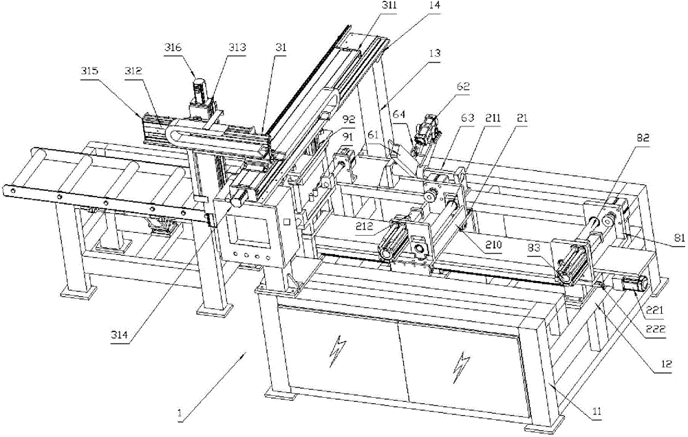
[0024] Such as figure 1 with figure 2 As shown, the cutting machine of the embodiment of the present invention includes:

[0025] Machine 1: has a three-dimensional frame 11 and a load beam 12 arranged in the three-dimensional frame, which is used for supporting the bottom of the machine;

[0026] Feeding mechanism 2: set on the machine platform 1, it has a moving mechanism 21 that drives the movement of the profile steel and a first drive mechanism 22 that drives the movement of the movement mechanism 21, and is used to drive the translation of the profile steel to transport one end of the profile steel to the cutting station;

[0027] Four-coordinate mechanism 3: installed above the cutting station, has an XYZ axis translation mechanism 31 and a cutting head installation part 32 installed on the XYZ translation mechanism 31 that can rotate 360° along the vertical plane;

[0028] Cutting head 4: installed on the cutting head installation part 32, used for cutting section s...


PUM


Abstract

The invention relates to a metal workpiece machining device, in particular to a cutting machine for automatic and continuous section steel cutting. The cutting machine comprises a table provided with a stereoscopic frame and a bearing beam arranged in the stereoscopic frame, a feeding mechanism provided with a moving mechanism driving section steel to move and a first driving mechanism driving the moving mechanism to move, a four-coordinate mechanism provided with a translation mechanism provided with an X-axis, a Y-axis and a Z-axis and a cutting head installing portion, a cutting head installed at the cutting head installing portion, and a control box connected with the feeding mechanism, the four-coordinate mechanism and the cutting head. The cutting head can be moved to different surface of section steel, can rightly face the surface to be cut of the section steel through rotation of the cutting head installing portion and accordingly achieves non-consistent cutting requirements of all cutting surfaces, the cutting requirements of section steel different in thickness can be also met by matching different cutting heads, and accordingly the machining demands of special specification of section steel workpieces are met by means of the device.

Description

technical field [0001] The invention relates to a metal workpiece processing equipment, in particular to a cutting machine for automatic and continuous cutting of section steel. Background technique [0002] In existing industrial equipment, construction facilities and other fields, metal workpieces of specific shapes are often required. Such workpieces are usually obtained by cutting the entire section of channel steel, angle iron, I-beam and other steel raw materials. In order to Raw materials are cut. The existing cutting methods generally include mechanical cutting and thermal cutting. Mechanical cutting refers to cutting the profiled steel by cutting knives, saw discs and other components. Fusion cutting. But existing cutting equipment that uses the above-mentioned principle has the following problems in use: [0003] 1. Mechanical cutting is generally used for materials with small cutting surface thickness or relatively soft materials. If it is used on materials with...

Claims


Application Information

Patent Timeline
Patent Type & Authority Applications(China)
IPC IPC(8): B23Q5/02B23D79/00
CPCB23Q5/02B23D79/00
Inventor 崔琦
Owner 广州精准机械有限公司
Why Eureka
Try Eureka