Drainage device for cabin of yacht

A technology for drainage devices and cabins, which is applied to ships, transportation and packaging, and pipelines for emptying/ballasting, etc. It can solve problems such as forgetting to discharge, and achieve the effects of saving manufacturing costs, less material consumption, and fewer operating procedures

Inactive Publication Date: 2015-09-23
YAGUANG TECH GRP CO LTD
8 Cites 3 Cited by

AI-Extracted Technical Summary

Problems solved by technology

[0002] At present, the common cabin drainage device quickly and manually drains the accumulated water in the section of the ship while reducing the use of power sources. The manual drain v...

Method used

Contrast prior art, control drainage structure by control box and be communicated with water pipe, and be provided with ventilating steel pipe 121 and compressed air joint 123 for compressed air injection on drainage structure, and ventilating steel pipe 121 is towards an end away from water outlet Inclined setting, the force of compressed air can be used to discharge the accumulated water in the bilge of the yacht through the suction of the water pipe, that is, the compressed air is injected into the drainage structure towards the water outlet, so that the pressure in the drainage pipe of the drainage structure is lower than that in the ship section. The pressure, and then generate the suction force of water absorption, suck the water in the yacht bilge into the hose, and automatically adjust it through the control box. When the water level rises to the position that triggers the high liquid level sensor, the drain solenoid valve opens, and the water will When the water level drops to the low level sensor, the drain solenoid v...

Abstract

The invention discloses a drainage device for a cabin of a yacht. The drainage device for the cabin of the yacht is characterized by comprising an electromagnetic valve (1), a water inlet pipe connected with the inlet end of the electromagnetic valve (1), a water outlet pipe connected with the outlet end of the electromagnetic valve (1), and a water suction pipe (4), one end of the water suction pipe (4) is connected with a water pipe (10), and the pipe diameter of the water suction pipe (4) is smaller than that of the water outlet pipe; one end of the water pipe (10) extends to a water inlet (51) located in a cabin base plate, and the other end of the water pipe (10) extends to a cabin bottom water outlet (61) located in a stern sealing plate. The water suction pipe (4) extends to cabin bottom water; the drainage device for the cabin of the yacht is characterized by further comprising a drainage structure (12), a ventilation steel pipe (121) is arranged on one side of a water pipe (20) in the mode of inclining in the direction away from the water outlet. The full-automatic drainage device which is wide in application range, reliable in drainage and capable of improving the quality of compressed air is provided. Certain beneficial effects are achieved.

Application Domain

Self-bailing equipments/scuppersVessel parts

Technology Topic

PipingElectromagnetic valve +3

Image

  • Drainage device for cabin of yacht
  • Drainage device for cabin of yacht

Examples

  • Experimental program(1)

Example Embodiment

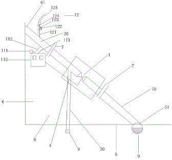
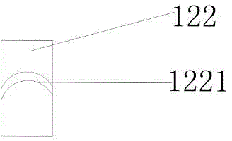
[0020] In order to better understand the improvements made by the present invention over the prior art, the specific implementations are described in detail below. figure 1 Shows a schematic structural diagram of a yacht cabin drainage device. The inlet and outlet pipes connected to the inlet and outlet ends of the solenoid valve 1, and the suction pipe 4 connected to the water pipe at one end but smaller in diameter than the outlet pipe. One end of the water pipe leads to the water inlet 51 on the tank floor, and one end of the water pipe leads to The bilge water outlet 61 on the stern seal plate; the suction pipe 4 leads to the bilge water, the cabin drainage device also includes a drainage structure 12, and the cabin drainage device includes a ventilation steel pipe 121 arranged on one side of the water pipe 20, and the ventilation steel pipe 121 faces away The direction of the water outlet is obliquely arranged on one side of the water pipe 20. One end of the ventilation steel pipe 121 away from the drain pipe is provided with an external thread, the compressed air joint 123 is provided with an internal thread matching the external thread, and the joint between the ventilation steel pipe 121 and the compressed air joint 124 is provided with an air leakage prevention device 123, The ventilation steel pipe 121 and the compressed air joint 123 are fixedly connected by bolts. As a preferred solution of the cabin drainage device, the included angle between the ventilating steel pipe 121 and the drain pipe 20 is 15°~45°, and the included angle between the ventilating steel pipe 121 and the drain pipe 20 is 28°. When the switch is turned on, the force that enters the drain pipe to absorb water through the hose and the water absorption assembly is the greatest, and the water absorption speed is also fast, that is, the accumulation of water discharged from the water outlet is the fastest.
[0021] The cabin drainage device also includes a control box, which is respectively connected with the solenoid valve and the alarm;
[0022] When the water level rises to the position that triggers the high level sensor, the drain solenoid valve opens, and the water is discharged under the action of gas pressure, and the water level drops continuously. When the water level drops to the low level sensor, the drain solenoid valve Shut down and stop water discharge.
[0023] The control box is equipped with a wireless module, which is connected to the remote terminal through WIFI.
[0024] In the improvement scheme of the above-mentioned yacht cabin drainage device, the bilge water outlet is 310-380mm above the waterline in height.
[0025] figure 2 show figure 1 Shows the schematic diagram of the structure of the anti-leak device 122. The connection between the ventilating steel pipe 121 and the compressed air joint 124 is fixedly connected by the anti-leak device 122. The anti-leak device is provided with a rubber sealing ring 1221, so that better and more reliable The shaft sealing effect can achieve a good and stable shaft sealing.
[0026] Compared with the prior art, the drainage structure is controlled to communicate with the water pipe through a control box, and the drainage structure is provided with a ventilation steel pipe 121 for compressed air injection and a compressed air joint 123, and the ventilation steel pipe 121 is inclined toward the end away from the water outlet. The force of compressed air can be used to suck the water in the bilge of the yacht through the water pipe, that is, compressed air is injected into the drainage structure toward the water outlet, causing the pressure in the drainage pipe of the drainage structure to be lower than the pressure in the ship section. Generates water-absorbing suction, sucks the water in the bilge of the yacht into the hose, and automatically adjusts it through the control box. When the water level rises to the position where the high level sensor is triggered, the drain solenoid valve opens and the water is discharged under the action of gas pressure. The level of water drops continuously. When the level of water drops to the low level sensor, the drain solenoid valve is closed and the water discharge stops. The entire drainage process is reliable, which is conducive to the safety of the front and rear equipment, changes the uncertainty of the previous manual drainage, eliminates the damage to the air compressor and dryer caused by the failure of water to be discharged in time, improves the quality of compressed air, makes the water discharged in time, and reduces the follow-up The load of the dryer and the filter is beneficial to improve the quality of compressed air, and the operation is convenient. The water level information and alarm information can be viewed in real time through the remote terminal.
[0027] The embodiments of the present invention are described in detail above with reference to the accompanying drawings. However, the present invention is not limited to the above-mentioned embodiments. Within the scope of knowledge possessed by a person of ordinary skill in the art, various modifications can be made without departing from the purpose of the invention. Kind of change.

PUM

no PUM

Description & Claims & Application Information

We can also present the details of the Description, Claims and Application information to help users get a comprehensive understanding of the technical details of the patent, such as background art, summary of invention, brief description of drawings, description of embodiments, and other original content. On the other hand, users can also determine the specific scope of protection of the technology through the list of claims; as well as understand the changes in the life cycle of the technology with the presentation of the patent timeline. Login to view more.

Similar technology patents

Workpiece welding positioning work fixture

ActiveCN112091504AReduce operating proceduresImprove workpiece assembly efficiency
Owner:SHANGHAI KONGBO IND

Classification and recommendation of technical efficacy words

  • Reduce material consumption
  • Reduce operating procedures

Heat exchanger network

InactiveUS20110120678A1reduce material consumptionless warp
Owner:AUTOKUHLER GMBH & CO KG

Safety-protection textile material flushing device for spinning

ActiveCN109680431AReduce operating proceduresGood cleaning efficiency
Owner:安徽省伊贝雅纺织有限公司

Account management method and system and terminal equipment

PendingCN109614781AReduce operating proceduresSolve the cumbersome login operation
Owner:PING AN TECH (SHENZHEN) CO LTD
Why Eureka
Try Eureka